Showing posts with label GWR Railcar. Show all posts

Friday, April 17, 2015

Waggly bit installed - on one side

Img_6051

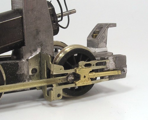
Attaching the crossheads to the connecting rod was achieved by using a small bolt through the back. The head is large enough to stay put and the thread poking through the front can support the crosshead arm. Plenty of solder holds all this lot in place.

The larger crossheads gave me unexpected problems with space behind the radius bar but attacking the top of them with files and a saw removed enough metal to sort this.

Everything is now working. I think the fly crank arm is a it long as the expansion link is leaning back too far. For the moment, it all works on this side so I'll carry on fiddling.

(If you are thinking I'm well versed on the technical terms, the trick is to look at the diagram on Wikipedia)

Thursday, April 16, 2015

Replacement crossheads

Brass crossheads

A few weeks ago, I mentioned that the GWR Railcar project had stalled as I wasn't happy with the whitemetal crossheads. Well, the good news is that at York, I was able to pick up some nice lost-wax cast replacements from Comet Models. LS8 if you are interested.

They aren't perfect of course, the days of a major show offering dozens of varieties of bits like this are long gone. Even at a show like York with the focus on kitbuilding, my options were London Road Models (nothing suitable) or Wizard Models (who oen Comet Models). To be honest I forgot Alan Gibson as I'd already bought the Comet ones by the time I was digging through the wheels on their stand.

Anyway, with a fit of fettling, these crossheads fit the railcar. There's a challenge getting the fat conrod end in the back and I'm still to attach the link on the front but I think I know how these can be overcome.

Pedants will point out that I've opened out the slide bars by just under a millimetre and that the piston rod is a bit fat. I don't care. If this works, that's all that matters, especially if it keeps working without falling apart!

Tuesday, March 31, 2015

Railcar motion problems

Railcar Motion 1

Regular readers will have noticed a distinct lack of action on the GWR Railmotor over the last few months. This is partly because I have been very busy with other jobs but mostly because it's time to look at the waggly bits and I've had to summon up some courage.

Deciding I couldn't put it off any longer, I dug out the kit and had a look.

First off, the motion bracket is supposed to be held to the chassis with a self-tapping screw. I didn't like that idea much. For a start it will be fuggly. Then, unless the pilot hole is drilled very close to the size of the screw, I reckon the whitemetal will distort.

No, I have soldered it using 100 degree solder and some no-clean-up flux I have for testing. Time will see if this goes green. It smells nice when heated but I'm not sure if that's a good sign.

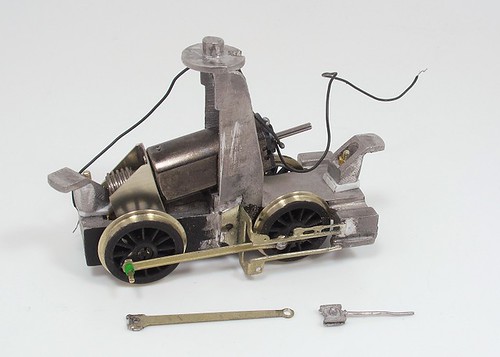
Next, the crosshead. Made of spindly whitemetal, I have a number of problems with it. For a start, the fit is terrible. After cleaning the slots and refining the slide bars, I made it move acceptably freely. Then I looked at how it should be attached to the connecting rod and find this information missing from the instructions and diagrams. I think you put the spigot on the back through the hole in the rod and then solder a washer on the back. It's an interesting idea but when this gives up the ghost, I'm going to be trying to solder in some confined spaces to fix it.

On the front, there is a link to be attached with glue. Of this hangs the union link and this is attached with brass pins soldered with normal temp solder. Hmmm.

I think the best idea is a lost wax cast crosshead. The channels that run along the slide bars are 4mm apart. Any suggestions for a supplier?
Friday, January 23, 2015

Preparing for the Walschaerts

Rods going on

The biggest worry with the railcar kit is all the waggly bits going on at the powered end.

I've tangled with Walschaerts valve gear before and learnt a few lessons. The key is to anticipate problems and try to build them out before you start.

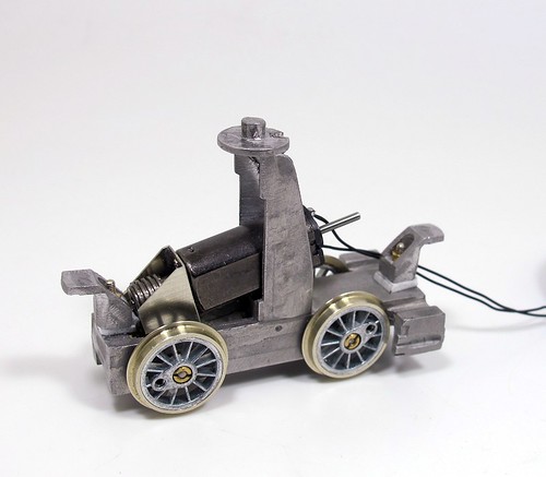
Most of the "fun" will be at the cylinder end so I've been trying to do things right here. First up, the wheels have been shimmed to remove all sideplay. It's going to be tight behind the crossheads and you don't want any sideward movement resulting in things banging in to each other.

Crank pins are fitted with a little superglue on the thread so they aren't going to unscrew themselves - it can happen and only results in badness. While I'm putting things together, plenty of black paint goes on as I'm not going to be able to take this thing to bits again to do that.

Thinking about the clearances, I don't use the Romford rod retaining washer as it's a bit fat. Some tiny brass jobbies with hardly any thickness are more suitable. Soldering these on, I've coated the rod with permanent pen to stop errant solder sticking where it isn't wanted. A bit of aluminium foil provides a little spacer and again, stops the solder in it's tracks.

The rods themselves are very nice. Etched in thick nickel silver, there's no laminating required. A tiny spin of a broach in each hole was enough to see everything running smoothly too.

Thursday, January 22, 2015

Railcar is go!

Motor and gearbox fitted

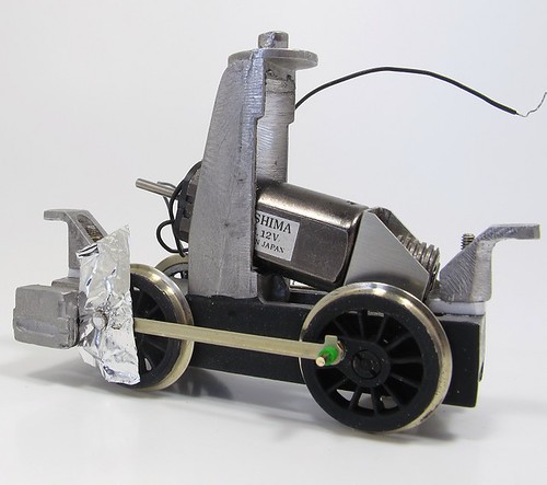
If NuCast made a GWR Railcar today, this is what the power unit would look like.

OK, maybe not exactly like this but more this then a DS10 that it's supposed to be fitted with.

The can Mashima came via a packing error with another kit. As it happened, I had a suitable motor to fix the problem and that left me with this one. The gearbox is a mystery but those are Romford gears in there with a 40:1 ratio.

Worst job was filing the hole in the frames to make it wide enough for the gearbox to slip in. I was terrified that the whitemetal lump would twist but I think I've got away with it.

Anyway, the power unit mow moves under it's own steam, so I can get serious with the waggly bits.

Saturday, January 03, 2015

Power bogie hangers

Power Bogie with fixings

With issues concerning the motor/gearbox combo in mind, I thought it might be a good idea to see how the power unit fitted in the coach body beofre going any further.

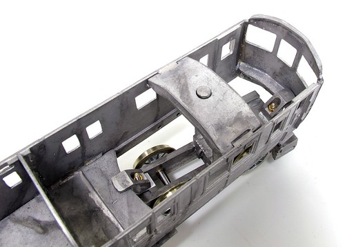
It's quite a nifty set-up. In the roof we have a pivot that takes the (considerable) weight of the body. Front and back of the power unit are curved sections inside the body which are pushed by raised horns on the power bogie. It's very like the method used by older RTR diesels - those fitted with Ringfield motors.

You'd hope all this slotted together, but no, the horns are too low. The top bits are at the same level as the curved body sections. Some plastic sheet packing raises them up a bit. Then I found that the front faces are too fat to fit within the curve - time for a coarse file to smooth them back until they went in and moved smoothly.

Once fixed, all looks OK. My railcar now rolls back and forth well enough. I haven't tried it on a curve yet, that will have to wait until I find a length of flexi track that hasn't been chopped up.

Still, there looks to be plenty of space in here so now it's time to find a motor and gearbox. Not as easy as in the past thanks to the reduction in kitbuilders and loss of companies who sell these bits over the festive period.

Power bogie fitted

Friday, January 02, 2015

Trailing bogie

Railcar bogie

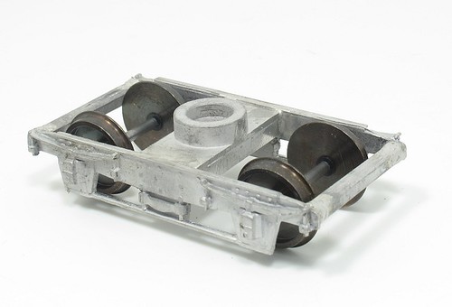
Back at the GWR railcar, the trailing bogie is a pretty simple, if fiddly, construction job.

The biggest problem is that if assembled as supplied, the axle ends are nowhere near being held by the holes behind the axle boxes. Filling these with brass bearings didn't help, they were too small for the holes.

A set of Peco nylon bearings did the job. These could be pushed in to the holes with some parallel jaw pliers using an old lolly stick to protect the casting. Left slightly proud of the sides, they held the axle points perfectly. The bogie now rolls with no resistance along the track.

Friday, December 19, 2014

Railcar body

Coach body

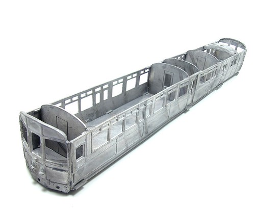
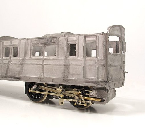
A couple of hours work with the soldering iron and here we go. Not a bad looking railcar body, but a pretty heavy one!

First, the sides and floor were made up using a ruler to ensure everything is in a straight line. This left tiny gaps around the centre doors. I'll live with these as a humped body is more of a problem. Running low-melt in from the back pretty much eradicates them anyway.

The floor slots in place and with a couple of partitions in place, all seemed to be going well so I added the second side followed by the rest of the partitions. The great thing about low-melt soldering is that you can tack bits together very quickly and undo the join if it need adjustment.

The ends take a little care as they aren't identical. The panelling under the windows is deeper at one end than the other. These castings took a little massaging with fingers to straighten them up but after this, the champhered corners fitted pretty well although I did need to cut away a little bit of casting below the floor.

Once happy, all the joins were seam soldered. It's still very flexible at this point, etched sides would be better in this respect, but I can certainly see how the model is going to come together.

Thursday, December 18, 2014

Body beginnings

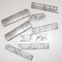
Body BitsPresumably due to the limitations of the moulding machines used by Nu Cast, the railcar body is supplied in twice and many bits are you might hope. Each side, roof and floor is a pair of parts to be joined by the builder.

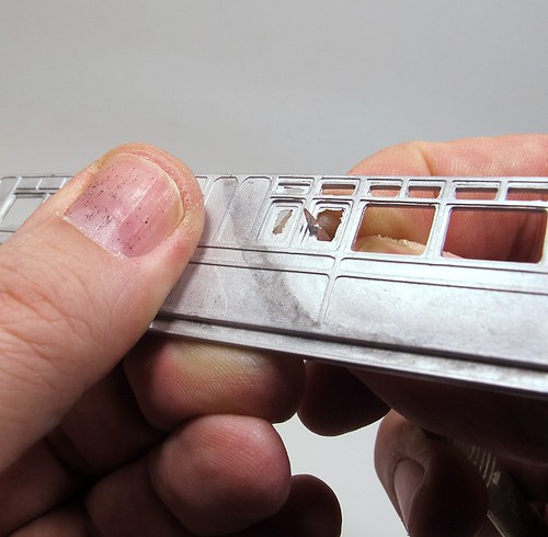
First though, there is some light flash to clean from within the windows. When mentioning cleaning up, most people think of files but I prefer a sharp knife for this job.

OK, carving metal seems a bit off but lead alloy is soft and Swann Morton blades aren't, so it cuts like butter. More to the point, the flash is incredibly thin so carving it away is a quick and easy job.

For a really nice finish, the same blade can then be scarped along the edge to finesse and polish any hint of mould lines away.

Cleaning thw windows

Wednesday, December 17, 2014

Railcar chassis

John asks: Have you ever thought of making a GWR railmotor? This is something that I I always wanted. I'm not looking for a lot of detail just an overall look and was wondering whether something could be made with the Hornby auto coach.

This isn't the first time I've been asked about railcars recently.

To start with John's question. Possibly BUT the body isn't the difficult part of such a conversion. Finding a suitable chassis with all the waggly valve gear bits is pretty much impossible. Maybe there is something from a continental range that could form a basis but it's going to be a lot of work.

Far better, if I'm honest, to await the RTR version from Kernow Model Centre. For £150 and a bit of a wait, I don't think you'll beat it.

However, this isn't a blog where I sit and wait for someone in China to be told by the bloke who used to run Banbury model railway exhibition what to do. No, I still have a Nu Cast whitemetal kit to build.

Motor fittedWhen I left the model, I'd put the powered end chassis together and was about to fit the mechanical bits. Easy, or so you might think.

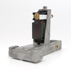
Well, persuading the motor to fit in the casting that appeared to be the mount took me over an hour. Lots of filing and scraping at the whitemetal to make the distance between the sides wide enough to slip the DS10 in place.

Eventually, there was success. With a couple of plasticard wedges, the motor turned under power and didn't rattle the sides.

Then I had a look at the gears. And there was a problem. Oh, yes, a good 'un.

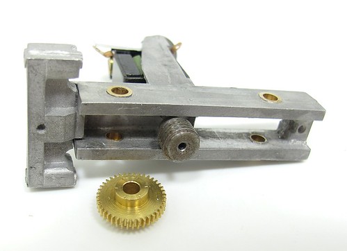
Gear won't fit
The worm gears is too fat for the chassis and even if I fix that, it's nowhere near the gear on the axle.
Re-reading the instructions, I spot a tiny note on the drawing showing the motor doesn't fit where I thought. It should be on the back of the casting. Arghhhh!
However, this isn't the solution you might hope for there are some issues.
First, it appears to be held in place with willpower and possibly fairy dust. Certainly no screw attachment points or castings are shown to do the job and nor are they evident on the model.
Second, the gears are still in different time zones and the worm isn't going to fit any better between the frames.
I'm sure there is a fix for this, probably a different motor/gearbox combo (no I won't use a SPUD at the other end, I want the waggly bits powered) but I need to know how much space is available. Therefore the next job is to build the body and see how all this lot hangs in there.


Thursday, October 23, 2014

4 wheels on my loco

 
The big worry with a whitemetal chassis is that the thing won't be flat. Castings have a tendency to subtly change shape as they cool and while that might not be an issue with the pretty bits, where accuracy matters, this is a bad thing.
 
You might wonder why if I'm so worried, I didn't replace the lump. Truth is, while there are only 4 wheels, I'd need to hang the cylinders and valve gear of it. More to the point, the body has to sit on top and pivot. Since the arrangement shown in the exploded drawing looks pretty promising (read, quite like the setup seen in old RTR) I don't fancy trying to re-engineer this.
 
Anyway, a quick check shows the chassis is flat so far. If it need a tweak, at least the metal is soft enough for this to be reasonably easy.
 
And in case you are wondering, the metal disk is from a computer hard drive. It's more robust than glass and flatter. I'm proper hard finescale like that.

Wednesday, October 22, 2014

Bushed chassis

 
I'm not sure what world Nu-Cast were operating in when they decided that the whitemetal loco chassis would provide adequate bearing surfaces, but in my world they were wrong.
 
With all those waggly bits hanging on the outside, I really don't want to have to strip the mechanicals down just because after a prolonged period of running, the axle holes are the shape of a Wheetabix rather than round.
 
So, after digging four brass bearings out of the pot you saw yesterday, I reamed out the holes in the alloy lump and glued the metal bits in place. Reaming took rather longer than I expected as the hole enlargement is greater than I expected but once done and with the holes countersunk, the bearings were pushed in to place and then pressed home in a vice. Only one needed a smear of runny superglue too.

Tuesday, October 21, 2014

Pot of bearings


When I pen a magazine article, one phrase I hope never to write is, "I got this from the spares box."

How frustrating is that for the reader? I might have a spares box able to provide the vital missing part but that's not much help to anyone trying to follow the project. Not unless I'm selling special spares boxes with all the rubbish you might need for modelling.

Actually, that's an idea. I bet they would sell. Especially if I got someone famous to brand them...

Anyway, on the blog it doesn't matter. So, here is my brass bearing jam jar. It's where I go when I need to stick some bearings in a chassis and the kitmaker hasn't thought to supply them. Once you've been modelling for a while, you build up this sort of bits stock and the building process becomes quicker and easier.

Mind you, I can't remember why I bought most of this stuff.

Friday, October 17, 2014

Traditional instructions

 
Traditional instructions. A great long parts list which you are supposed to check through before starting - and never do. Well I don't anyway and even if I did, it wouldn't do me any good here. It's not like I can ring the manufacturer up for spare parts. Not unless I have a special old telephone anyway.
 
After the list, lots of words in great big slabs of text. The sort of great big text slabs that people tell me they prefer in magazine article rather than all those new fangled pictures and boxes and stuff. The sort of thing that every other type of magazine outside toy trains has. The ones that sell in any numbers anyway.
 
Sorry, moaning. Seriously though, I hate digging through this stuff. At least give me a bulleted list so I can tick stages off as I work.

 
This is more like it. A great big exploded diagram. All the parts shown and clearly enough that I probably won't bother reading the words.
 
Sadly, producing this sort of diagram is horribly expensive now. Draughtsmen aren't easy to find and those you can hire want hundreds of pounds per day to draw simply because they know they are worth it. Why can't people work for three shillings, a bowl of porridge and a day off being horsewhipped? The good old days have certainly gone...

Thursday, October 16, 2014

What's in the railcar box?


I don't know why, but when I first opened up the box, I was surprised by the cast whitemetal sides. In my mind, I'd expected etched brass parts for these and had already started to ponder how I would form the tumblehome - something I've had little success with in the past.
 
No worries here. Wrapped in tissue paper are cleanly cast whitemetal bit ready to be slotted together. OK, so the moulded handrails need to be replaced but that's not a great problem.
 
 
Where I expected etched, I got whitemetal. Where I wanted etch, I got whitemetal too. The chassis is a lump of the stuff plus etched waggly bits and a load of fittings. the brass pins for tieing waggly bits together could be interesting. I'd have expected rivets to squash, so some neat soldering will be required here.
 

Wednesday, October 15, 2014

GWR Steam Railcar


Back in August, I suggested that since I was going to be away from the workbench for a goodly chunk of October, I ought to build a kit to entertain you for the duration.

You voted, and the clear winner was the GWR Steam railcar.

Now, you can probably guess from the slightly random nature of the posts so far this month just how far I've progressed with the build, but we'll have a look anyway.