On Sunday, I showed the lifeboat pin cushion as I acquired it and after a week of sporadic work, here is is in it's shiny glory.
Projects like this are a bit of fun and also a useful chance to try new techniques and materials. In this case it was gloss paint. Not a big stretch I hear you say but this time it was to be brushed on rather than sprayed. I reason that this is how the model was originally painted so for a restoration project, I should do the same.
Colours are all from the Humbrol rage: Red, Dark Blue and Ivory.
I cheated a bit with the red and used a base coat of matt paint before a couple of gloss layers. From many buffer beams I know how hopeless the covering properties of this stuff are !
Rather than use pure white, which I think would look a bit stark, I plumped for ivory. The boat arrived with cream paint but a test coat on the top showed this would look terrible. I doubt that the original paint was cream, it's just turned that way through the years. These boats were around when this model was popped out to the souvenir shop so I can't really see them getting it wrong ! Again, the covering properties let me down and three coats were required to get a decent depth of colour. In retrospect I'd have preferred to spray this as the rope detail has been filled in a bit.
The blue was the final challenge. I masked the bottom edge even though there is a line in the moulding to delineate the colours. The paint went on OK and by using a puddling technique (applying a thin coat and then piling the stuff on on a pool) I managed to fill it in with a single coat. Luckily gloss takes a while to dry and spreads a little to fill the areas between the raised detail. Of course it's vulnerable to dust during this phase so all the model was left under a box to keep particles out.
I'm please with the results. Hand painting gloss isn't something I plan to do in the future - it's back to the airbush for me ! Alternatively I will paint in matt and gloss varnish. Still, I think I've save something from the bin. Collectors will probably tell me it's value has been ruined by my work but that's their problem.
Saturday, October 31, 2009

Friday, October 30, 2009
Painted chassis

Someone recently asked me what happens between a locomotive chassis being seen in the brass and the stage you see here - the same thing painted and with all the mechanicals in place.
Well, since I last blogged this part of the loco, I've removed all the moving parts and given it a thorough clean up in the sink. After this a hairdryer ensures all traces of moisture is removed before a coating of Eastwood Etching Primer
Next I used "Weathered Black" as the base colour - it's not really black but a charcoal grey and looks great on a model that is going to get a good coat of muck all over it later. This paint needs 24 hours to dry to a fully hard state. If any work is carried out before this happens it's very easy to damage it. You can get away with it but it's better not to try.
All the bearings require re-reaming to remove traces of paint and primer. At the same time I like to give the axles a quick wipe with fine emery paper to shine everything up. The wheels go back in and the rods on. If all is well after a quick test the retaining washers are filed down and soldered in place.
All soldering at this point makes use of Carrs Red Label flux - a non-corrosive that doesn't need to be cleaned off. I can't dunk the chassis in water any more ! This applies to the brake gear - hangers and pull rods too. The later are a bit of a problem as they have to bend slightly over the firebox but you can't tell when the model is on the track and they do fill up the space down there. Of course I remember the "good old days" when you wouldn't worry about brakes never mind the ancillaries. Much easier !
Thursday, October 29, 2009
TV Review: James Mays Toy Stories
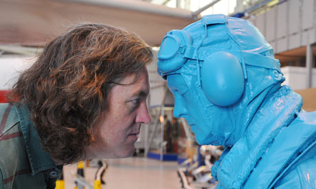 James May (the good one off Top Gear) has been appearing in various bits of the media for the last few months thanks to the BBC press machine gearing up for his new series "Toy Stories". So far we've heard about the Plasticine garden and Lego house. This week we finally saw the results of all this work with the series making it to air. Literally in this case as the toy in question being Airfix.
The programme followed a suitably (for the telly) simple narrative. May has spotted that plastic kit modelling (the show used the word "Airfix" as a verb throughout) has become an adult occupation. Kids have other things to to and actually making things is sneered about. He had decided to try and reintroduce the hobby to "da kidz" through a series of stunts culminating in building a full size Spitfire from a kit.
Now I have to admit I hate kids in TV shows but these were less loathsome than most. The first kit they were presented with was the Golden Hind. It was the first plastic kit manufactured by Airfix so this might seem sensible. Trouble is, it's a horrible kit full of fiddly bits. As you have a presenter from a motoring show, why not start with a car kit ? The results didn't encourage anyone much.
Next up were tanks. Anyone who has made one of these kits up will know that like the Hind they have loads of fiddly parts plus rubber tracks that you can never get to bend properly. A bit of TV trickery showed Dads helping their offspring to make the models and at this point the show had a great point to make but left it alone - the kits became a joint production and to descend in to Guardianese - a bonding activity. I like this. For lots of parents, computer games are divisive. The kids are faster at picking them up and becoming proficient. Mum and Dad therefore are excluded and the generations develop separate activities.
The tanks led to the first "stunt" where the finished models were taken to a tank driving range and the kids got to drive the real thing. This was the first point where you really despaired of modern youth. Given the chance to have a go at the controls of a tank, they weren't really interested. Good grief kids YOU ARE GETTING TO DRIVE A TANK , on a school day, for the telly. I never got the chance to do that.
The models were then used is a stop motion made film where most were blown up - I'm surprised May's mention of dismantling fireworks to do this in his youth made the final edit. Except one. Because the builder was proud of it, had made a really nice job and didn't want ti destroyed. Personally I would advise any government minister to find this child and give him a top job as he's obviously unusually well adjusted.
Along side all this there was a strand showing the creation of the full sized kit along with some historic stuff about Spitfires. The later was nice and the May's inability to speak once he had been allowed to fly a 2-seat Spitfire was obviously heartfelt. I liked the giant kit making bits as well - the guys trying to turn the idea into reality obviously had a tough job and I suspect they may have wondered why they agreed to take it on. It's not like the advertising will have generated any more sales. If you want a full size fibreglass Spitfire on a stick, you'll find them after all.
The penultimate stunt was building 1:24 Spits in a Coventry car plant. I know where it is as I broke down outside it once in my campervan... Anyway, by this time the kids were getting it. Sat beside an assembly line they were able to employ the same techniques to produce creditable models.
All this lead to the finale where the full size kit is unveiled. OK, it wasn't quite a pure as planned, the wing assembly had to be braced with metal for example, but the results were impressive. TV trickery to the fore, I think we were meant to believe that assembly took place over a day when it obviously didn't. Likewise the kids didn't do the whole thing but they did appear to be involved a lot of the time. May did his "old bloke who doesn't get youth culture" bit by not knowing who Beyonce was and generally played up his TV persona. By the end though the resulting "model" was impressive. Cosford are very wise to agree to keep it in the museum as it ought to generate a few extra people in the door for the future. Some of the kids even seemed to appreciate the hobby and get the message. OK, this might just be what you get by pointing a camera at them, but maybe just one or two will try again. And perhaps one or two parents will want to help.
I liked this programme a lot. OK, for me, it's preaching to the converted but the producers managed to walk the tightrope of popularity without dumbing the show down so much that I think Airfix modellers are being laughed at or insulted. This probably wasn't a cheap show to make but personally I'd swap the entire output of Eastenders for it any day.
Toy Stories on the BBC web site
Wednesday, October 28, 2009
Gearbox in cab
or rather, gearbox not in cab. Sometimes fitting the body over the mechanicals on a model locomotive can be a whole heap of pain with much hacking away inside the shell. I've had to resort to a dental burr in a minidrill inside whitemetal locos more than once !
On the bulldog, a few minutes work with the piercing saw to remove a couple of tabs behind the sandbox hole was all that was required. After this a little wiggle sees the motor tuck into the boiler and the gearbox "step" nicely coincide with the front edge of the cab. Hopefully the backhead won't even need any work to clear the gears.
I love it when a plan comes together !
Tuesday, October 27, 2009
Chassis with gearbox
For a goods engine you need lots of low down grunt from the motor and gearbox, and not too much top speed. The Bulldog locomotive uses a Markits MM-2L 2-stage box attached to the biggest Mashima motor I could fit in the boiler (don't ask me which, I can never get my head around the number nomenclature).
The 'box comes as usual as a flat etch in surprisingly hard and thick nickel silver. It's cut out and folded up. The end and back plates are soldered in place, I wasn't wild about how well they fitted but solder filled the gaps, then the bearings go in. A quick scrub to remove the flux and the other parts can be fitted.
Of course things are never quite that easy. I wanted to mount the motor at 90 degrees to the lugs and holes provided so a couple of new holes were drilled to allow this before forming. Luckily I allowed a bit of movement as the motor has to be about 1mm above the centre line of the hole provided for the shaft and boss, although this doesn't have to be altered, for the gear mesh to be perfect.
Loads of spacing washers are on the etch yet only two were required to keep the idler gear in position. I fixed the shaft with a drop of superglue and removed the grub screw from the gear so this rotates on the shaft. I find this easier than trying to allow the shaft to turn and then working out how to keep it in position horizontally. Mind you a couple of nickel patches over the ends would have worked in this case as it is very accurately cut to length.
Fitting the box in wasn't too painful either. Despite being pretty bulky, only one frame spacer needed shortening whilst the rounded edges of the gearbox front were squared off to get them in against the back spacer.
The whole thing ran smoothly first time, assisted by the very nice (to my untrained engineering eye) brass gears.
Monday, October 26, 2009
Sticking the body together
 "With all the big bits built, all I have to do is stick the body together", I thought, "Simple."
Well, the firebox went on first. The trick seems to be that it goes inside the splashers, not over the top of them as I'd first supposed. At least it fitted so nicely this way so I assumed I was right.
Next up was the boiler/smokebox unit and aside from a touch of fettling at the front around the smokebox saddle. I think the inner saddle needed to be a touch further forward than I mounted it but the problem was quickly solved with a small file.
Finally to the cab. The dry run showed up some badness going on. Somehow the firebox overhung the rear splashers. Only by half a millimetre but that's enough to look 'orrible. There was a gap around the bottom.
Much head scratching later I still couldn't work out what had gone wrong. Of course this didn't mean I could just ignore it, nor was any solution involving filler on the agenda. In the end some gentle filing with a fine needle file took off the excess. The metal is very thin and the strokes had to be along the length of the metal rather than across it. After this, the cab fitted perfectly.
With everything tacked in place a lot of time was taken up looking along the boiler from the side and top. Trying to figure out a way to measure if the barrel was parallel to the footplate and generally looking for a lack of squareness. Once I was happy, proper seam joins held everything in place.
Despite this, it still all looks square. Which is a relief.
Sunday, October 25, 2009
Lifeboat rescue
I'm a bit of a sucker for lifeboats and lifeboat memorabilia. Worse, I often feel sorry for old and battered things and want to repair them no matter how much more sensible it would be to check them away.
So, when I spotted this little lifeboat pin cushion on eBay a few weeks ago it ticked all the boxes. Ten pounds later I was the proud owner of a valuable antique. After a few days my ship came in, 10cm long and as you can see, a little bit battered.
Nevertheless, we have the technology to revive this boat. Fortunately the cushion part is in good condition and none of the sawdust it's stuffed with has leaked out. That just means I need to repaint the lead (as in lead soldiers) casting. First stop was a dunk in some Nitromoors to get the remains of the old paint off. The basic casting is lovely and sharp. Better still, all the lines delineating the different colours are moulded in so no masking required !
I'll be hand painting this as it was originally. This is partly for authenticity but mostly because it's going to kick around my modelling bench while I work on other things being picked up and put down for odd moments.
Saturday, October 24, 2009
Boiler progress

I actually had to read the instructions for this bit !
The boiler arrives as two bits of tube and a wrapper. Sadly, and the reason I had to read stuff, the shorter one isn't shown on the diagram.
Anyway, this is is how it works:
- Take the shorter tube and slit it along the length with a fine saw.
- Slide this over the other tube and wonder why you weren't given telescopic bits instead. Tack solder this in place - lots of heat required.
- Fit the smokebox saddle towards the front of the boiler.
- Tack the wrapper from the bottom of the saddle and wrap it around the boiler, tacking it at the other end.
- If all is well* and everything is square, run lots of solder around the back edge and front. Plenty of flux and heat from the pencil gas torch required for this bit. Burnt fingers too !
- Get the fibreglass stick out and start burnishing all the excess solder away. Obviously as an expert, I didn't have much of this...
If all is well, make up the front angled plate. I don't think it is on the etch so I used a bit of scrap, making sure the smokebox door will fit with it in place.
*If all isn't well, hold it over the gas hob to release the solder joints.
Friday, October 23, 2009
Chisels
I need to hang some wooden doors. This will involve hacking out bits of wood to allow the hinges and catch to be fitted. With my new found "skill" from all that work at college I reckoned that some nice new chisels would allow me to gracefully carve away to produce a top quality job.
So, off I trot to Homebase and there is a nice pack of 4 chisels plus sharpening stone and oil for 25 quid. A bargain. Probably too cheap in fact but as they were from the well respected firm of Stanley, I reasoned they would probably be good enough for me. I know someone will probably suggest they I should be using some exotic Japanese woodworking tool that costs several hundred quid, and I'd probably find it wonderful but pragmatism rules at the moment.
Anyway, the door work starts. These are top quality doors from a proper builders merchant. Since the wood is good, hacking half a cm off the bottom is hard work. Planing 3mm off the side isn't as the material cuts beautifully, especially since I used my new oil stone to sharpen the blade like wot I was taught.
Hinge time arrives and after marking out I prepare to use the new chisels and get a surprise. The reason there is sharpening equipment in the box is because the things turn up blunt. Not usable at all, in fact one has a light bur at its tip.
OK, so fixing this isn't a problem. A few minutes sees them all ready for use. I just wish I had known from the outset. Once I am working on a job, apart from tea breaks (Note for foreign readers, tea breaks are a legal requirement on all jobs in the UK. Certain roles, such as builders, have minimum sugar levels in the tea as well), I like to keep going. Stopping to prepare tools is not appreciated at this point.
So, if you go down to the DIY store today, beware of a great surprise and make sure you check the tools are sharp before starting work.
Thursday, October 22, 2009
Box of fire
This bit of the Bulldog locomotive is fun. The firebox comes out of the fret as a single fold up item. Sadly it's the first example of poor design I've found in the kit - in my opinion anyway.
The idea is that you fold the front and back down, then bend the sides around these. The problem is that the front and back don't sit properly in so that the sides hit the edge of the etch. Instead they are half way there.
With care you can just about tack the metal bits together but it would probably be a better idea for those not confident of their abilities to remove the front and back and then tack them into position under the firebox top. This then acts properly as a wrapper and runs around the edge.
Having said this, it can be done as supplied - I did it and the results sit very nicely on the footplate with the cab. These parts aren't fixed in place and yet the fit is pretty good already, a sign of an overall good kit.
Wednesday, October 21, 2009
Midlands Model Engineering Show 2009

Aren't concrete floors hard ?
At least that's what I know after spending a couple of days standing on one at the model engineering show this week. As part of the KMBC stand my job was to hang around chatting to the public and try to answer questions about the boats on display.
All this went well. The show actually lasts 5 days and I was only there for two but I still had plenty of time to look around and marvel at the exhibits. To be honest, I still feel a fraud art these events. The stand opposite was host to the most wonderful 3 1/2 inch gauge model of a GWR Manor locomotive scratch built from brass and steel. We had kit built boats made from fibreglass and plastic.
On the other hand, compared to most people, we are at least making stuff and not sitting watching telly. The visitors seemed interested and we have several potential new members for the club. Being so close to the venue is a big help as we can say that the lake is a mere 7 miles away from where you are standing. That's important ans it should allow us to mop up all the potential model boaters in the area.
I had to be rescued at one point from a couple of old guys who wanted to whinge that the organisers had once been rude to them when they had turned up an hour early to pick up a model in previous show many years ago. Their moan was that all he was interested in making money and that they would never show any of their models there again. This was obviously something that had rankled for many years and I suspect that gripping about this was something they looked forward to every year. Sadly they missed the point - the ME is a commercial show. If it doesn't make money, it will closes. If you want something "better" then you have to organise it yourself, just like the model railway world already does. Truth is, these guys couldn't see that while they might miss being able to show their models (and get in for free), the rest of the world wasn't that bothered. More to the point, the option they seemed to prefer was for the show to close. That way they would have "revenge". And we all would have no show.
Aside from the moaners, there were lots of models on display. Quality was again amazing and well beyond when bodgers like me can hope to attain, not least because we don't have the patience to put the thousands of hours into a single model. I've taken pictures as best I can to show some of the things I liked.
Other highlights, well the brick making machine was impressive. It is a press that compacts dry clay dust into miniature bricks suitable for dolls houses and model stationary engines. I have a few samples to try in the garden railway. More on the website
There is also a neat pin-striping tool. I've seen the demo many times but during a lull in the crowds managed to have a go myself. It' really works - better than a bow-pen anyway. The results are clean and consistent. I think the smaller wheels would even be useful for model making purposes even though it's better suited to full size stuff and larger model engineering. Not cheap, but then you can feel the quality. More on the website
Talking of cost, it still scares me how little completed model engineering projects sell for. Looking at a 1/4 scale traction engine selling for £21,000 you might disagree, but if you tot up the number of hours the model will have taken to build, I bet the hourly rate was less than the minimum wage. Sadly, I still had to resist. Even the lovely 8 inch high signal lever kit which would look so nice on my desk....
Tuesday, October 20, 2009
Uckfield Model Railway Exhibition 2009
 Before writing this post I thought I'd re-read last years entry on the show. When I did I realised that I'd pretty much need to say the same thing again this year.
First up, the quality of the show was excellent. Not just good, but really excellent. The layouts were great and so was the trade, some of my expenses were quickly exchanged for a diesel railcar kit that I couldn't resist and New Eileen helpfully lightened my wallet too.
The crowds were pretty good and they stayed all day. Saturday morning was packed as expected but even Sunday afternoon was well attended. I understand that the treasurer is happy, or at least as happy as treasurers ever are ! Things were very chatty, which was to be expected since we had a prototype 10 miles away from the show. Several people knew the line very well and I've been offered more information on the line. We were both pretty hoarse by the end which can only mean we've had a good time.
Our accommodation was different from last year but very nice. A huge comfortable room with en-suite was accompanied by a fulsome breakfast. If I'm being picky, the bacon was a bit pale for my taste on Saturday but Sunday saw this swapped it for an extra sausage making for a satisfied full tum.
We were looked after extremely well. Tea was delivered every 7.5 minutes on Saturday (slightly less on Sunday but we still drank a gallon each) to the layout. I loved the lunch which featured the best banoffee pie I've ever eaten. Not being a fan of lasagna (his loss), my Dad made other arrangements on Sunday and on noticing that the ticket hadn't been used, someone took the time to check all was OK (it was) which just shows superb attention to detail and care.
Saturday 's social was good fun. The venue was more spacious than last year and the food and company were excellent. The quiz, still being written at 1am that morning apparently, was good fun too. The picture round of identifying famous places from Google Earth shots was very clever. Eurodisney completely fooled us all.
Basically, it was good. If you get the chance to visit, do so. If you are really lucky and get the chance to exhibit, jump at it.
A slightly patchy set of photos of the show, with comments.
Michael's Blog which tells you more about the layouts.
Monday, October 19, 2009
Top Gear corner
 Over the weekend, I had a hire car. A Vauxhall Insignia. It's quite exciting for me to drive a modern car. Therefore in the spirit of Clarkson, I feel a review coming on:
Pros:
- The car had all the toys. I mean ALL the toys - the steering wheel had more buttons than Jensons. The radio was more complicated than my hifi. Headlights started to work automatically, good news when you have forgotten to work out to to switch them on. There was cruise control too but I couldn't work out how to operate it.
- The seats were comfortable.
- 6 gears - yes 6. Why ? Old cars managed with 3, here I get twice that, or more if you count reverse. They had even put the gear stick in a proper place.
Cons:
- The handbrake is in the wrong place and can only be operated by a contortionist.
- There is a box behind the handbrake which now has a dent the shape of my elbow.
- It's silver. The colour people choose when they can't be bothered to choose or have no imagination.
- I think there is a hole in the petrol tank, or it drinks fuel like I drink tea.
- There is no space in the back. I mean look, Hellingly Hospital is a tiny layout no longer than 6 feet long and yet it still struggles to fit in the back. This is no tiddly shopping car either, it's a proper repmobile which will in theory hold 4 people. When will car manufacturers think about the railway modeller market ? I mean we need space to move train sets and that is what matters, not rubbish like ride quality or lights or performance. I want a box that moves stuff. A bit like my campervan but suitable for the M25.
Can I have a job on the telly now ?
Sunday, October 18, 2009
Announcements
 It seems at next years exhibition (16th and 17th January 2010, put it in your diary) we will have access to a public address system.
This begs the question, Who do we get to make the announcements ?
Obviously it needs to be someone with a suitable "broadcast" voice who can enunciate properly and doesn't sound embarrassed to have been given the microphone. Not someone who sees it as an opportunity to order the crowds around either.
My though was that there are a whole load of suitable people to be found in sunny Stratford-upon-Avon. Specifically the RSC. After all they only work in the evening so they've nothing better to do during daylight hours have they ?
Then it occured to me. Wonderful though the diction may be, the luvvies will probably insist on fiddling with the script to make it sound more Shakespeare. Yet by chance, the man himself wrote quite a lot that is suitable for our use:
- P4, or not P4: that is the question.
The slings and arrows of outrageous tolerances,
Or to take arms against a sea OO. - If you prick us with a knife do we not bleed? If you tickle us do we not laugh? If we mistake liquid flux for tea do we not die? And if you wrong us, shall we not go on the interweb and moan in forums?
- There are more things in the bottom of my toolbox, Horatio, than are dreamt of in your philosophy.
- But, soft! what light through yonder window breaks? It is the east, and the DCC directional lighting system is working.
- A horse! A horse! My kingdom for a Scammel mechanical horse!
- Cry "Havoc," and let the public at the second hand stall.
- All the world's a layout,
And all the men and women merely Merit figures. - Neither a borrower nor a lender be;
For you'll miss that screwdriver when it doesn't come back, - The finescale modeller doth protest too much, methinks.
- For 'tis the sport to have the engineer
Hoist with his own petard... - Now is the winter of our discontent
Made glorious summer by this trip to York show, - Once more unto the breach, dear friends, once more,
Or close the wall up with some Slaters products! - Is this a scalpel which I see before me,
The handle toward my hand?
Ouch, wrong end ! - The attempt and not the deed
Confounds us. - By the pricking of my thumbs,
A new brass loco this way comes. - Out, damned paint spot! Out, I say!
- But love for the GWR is blind, and lovers cannot see
The layouts all look the same to me. - Misery acquaints a man with strange club members.
- If music be the food of love, fit a sound unit in that loco;
- Things won are done; joy's soul lies in the doing.
- It is a wise father that knows his own child would really like a train set.
- There is nothing either good or bad,
but thinking makes it finescale. - Though this be madness, yet there is method in it.
- Good night, good night! Parting is such sweet sorrow but the show is now closed so GO HOME !
Bonus points if you can spot the ones I didn't have to rewrite...
Saturday, October 17, 2009
Locomotive cabs
 First decision - which cab to use ? The kit provides two different cabs for this particular locomotive. Without a picture to guide me, I had to guess which one to use and then check if I'd got it right.
The options were, a plain cab with beading or a more modern version covered in rivets. I plumped for the later as I think the other is for an earlier loco. This will be finished in LMS livery and I suspect that they'd been rebuilt by them. Anyway, it's a more attractive version, looks better with the rivet strewn front, to my eyes so that's what I used.
Despite only having two parts at this point, this is still a bit of a beat to put together. Both parts are half-etched and therefore thin. Theres also a load of detail that must on no account see any solder or it will disappear. And once part has to bend around the other.
I started by marking the centre of both parts, lining these up and tack soldering in place. Then the sides were carefully formed with the aid of suitable sized brass rod and pliers. The wrapper doesn't naturally bend in the right places as the cab side cutouts are weaker than the top where you want the curve to be. Gently massaging the metal did the job and after a few more tacks I was satisfied that both sides reached the bottom of the front (not a given) and it looked OK from all angles. And fitted the footplate.
After this the tacks were extended to seam the joints with the minimum of solder and I checked it all again.
Best of all, it seems I did pick the right cab. so I don't have to do it again.
Friday, October 16, 2009
Model Engineering show set-up
 I'm doing two shows this weekend. As well as appearing at Uckfield with the Hellingly Hospital Railway, I'll be taking part in the Midlands Model Engineering Exhibition around the corner from where I live.
Set up was last night and we took along a couple of puffers plus Tomsk and a tugboat. These joined the KMBC stand which is, as usual, packed with very good things for all to see.
It's funny appearing at this sort of show. I feel a bit of a fraud since the modelling I do isn't really model engineering. OK, I tinker and make things but on the opposite stand is a GWR Castle made from scratch in proper steel and brass. That's engineering - the man has used a lathe, a tool that separates (in my head anyway) the men from the boys.
Still, I suppose we do have to build the boast ourselves. There is only one ready to run boat on the stand and that has been extensively detailed so you can't tell which one it is.
The clever trick of being in two places at once is being achieved by only attending the show in person on Monday and Tuesday. Other club members will provide cover for the other days. It's still a bit odd to have a show open during the working week but there will doubtless be coaches in the car park ferrying aged engineers from all parts of the country. With a bloodstream that's significantly steam oil, these guys will arrive and scrutinise the exhibits then leave with rough castings and sharp implements planning the year aheads projects. And you know what ? They will get them done too. You don't need a computer for brain training, just a workshop with tools and the desire to make things - that's what keeps the mind active and the eyes twinkly for years to come.
Thursday, October 15, 2009
Wheel cleaning
Part of my preparations for any exhibition is a wheel cleaning session a few days before we pack up. I'll admit I quite enjoy this bit - stick all the locos upside down in the trusty Peco cradle, give them a dose of 12V and shine the treads up with a fibre pen. Whirling wheels and disappearing dirt is fun. Useful too as the last thing you need after a long drive is running problems caused by poor electrical pick-up.
The session will also show up any issues with the locos themselves. Luckily they all seem to be behaving themselves, at least when inverted !
The only problem is one that is unique to the Hospital stick, slow running. On a layout the locos fitted with 108:1 gearboxes are wonderful. They drift around the track and take ages to go from one end of our short boards to the other. When cleaning though, what you want is whirling wheels and yet even on full power they rotate sedately and thus take 3 times as long to clean !
Every silver lining has a cloud, as they say...
Wednesday, October 14, 2009

Things I learned building the Bulldog locomotives footplate:
- You shouldn't bend the splasher faces up before putting on the valances. It makes balancing the resulting sheet upside down a whole lot more difficult. Not impossible thanks to a combination of bits of wood and lolly stick, but more difficult.
- The supplied plan is not 4mm scale. It's just a little bit bigger. That is quite annoying.
- The valances fit behind the the rear beam and not at the side of it. Do this and they are too wide for the front buffer beam.
- The bolts are 10BA. More than adequate and a lot easier to fit than my normal 8BAs since the holes don't need opening out.
- The splasher tops are fiddly but doable. The trick is to put the first sharp bend in place, tack the strip and then work it around the splasher face. Tiny amounts of solder mean little cleaning up is required. I'm quite pleased with this.
- The chassis is a touch too long but can be shortened easily enough to fit. About 1 and a bit millimetres I think. Just make sure you take it off the right end so the wheel centres and splasher centres line up.
Tuesday, October 13, 2009
Chassis testing

Having a layout handy is allowing me to test the Bulldog locomotive chassis on real track. This is better than a test track because it has curves and checkrails and lumps. It's very easy to build a chassis that won't go around corners 'cos you haven't allowed enough sideplay and these sort of problem often only come to light when the loco is pressed into service. Most of my stuff gets a run on a layout long before paint is applied if at all possible - it's so much easier to wield the soldering iron or files when you aren't worried about messing up the paint.
As it is, this chassis traverses the curves OK but I'd like to get some power onboard for a proper test. A little more side slop might them be needed, mind you, these curves are on the tight side - the Terrier binds a little when I run it and it's got a similar wheelbase.
You'll notice the tender has advanced a bit too. The axleboxes are on and thanks to some filing on the chassis and removal of axle pin points, it's sitting on its wheels too. I'd be intrigued to see how a P4 modeller would cram everything in under there as the OO wheels are a squeeze. I suppose it could be done but the faces of the wheels would be perilously close to the back of the outside frames.
Monday, October 12, 2009
Wonkiness
Ever since I built the Hospital railway, the fiddle yards on the ends of the baseboard have been wonky. As you can see from the photo, they slope down around 10mm over their length. Wagons roll to the outer ends on their own.
Worse though is that the front looks wobbly. The front walls don't line up nicely with the edges of the scenic area and ruins the nice tidy finish I've always wanted. Part of the problem is that in order to fit the boards in VW Beetle (proper one, not your new fangled funny bodied Golf) the fronts were hinged so that the boards could be screwed together into a small box.
With the Beetle off the road and bigger cars in use, there is no need for the folding fiddle yard front, It's fallen to bits anyway. So it's being replaced with some nice bits of 6mm plywood. Being solid, they can be fitted with furniture joining blocks so the tops can be secured to the top of the main baseboard.
Result: Well the square still isn't quite, but it's a whole lot better. From the front the display looks nicer too.
Sunday, October 11, 2009
How tall should a layout be ?
In preparation for a trip to Uckfield model railway exhibition next weekend, the layout has been dragged out of storage and we've been looking at a few repairs and improvements.
As part of this, serious consideration has been given to making a new set of lags for the layout. The current ones are spindly and a bit fragile but they seem to work when not being patched up. Future layouts though will be getting something a bit more sturdy.
Which raises a question - how tall should a model railway layout be ?
The Hospital is about 95cm (37 inches) off the floor. I think the others we've built are similar. Reading the latest issue of Narrow Gauge and Short Line Gazette, one of the contributors home based layout is a whopping 132cm (52 inches) high - that's taller than the worktop I have for layout building 111cm (44 inches). The later is tall enough to cover a hot water tank and also put the model at a pleasant height for me to work at.
Now at 6ft 3 (190cm) I'm taller than average (5ft 9ins or 175cm) but not by much. Standing in the pub there aren't many people shorter than me. To view a model I prefer it to be at a height that doesn't require me to bend down too much. Aside from being uncomfortable, if I bend I stick out into the aisle of the show and take up more than my fair share of floor space !
Of course I could just built layouts for me but since they are intended to be for exhibition use, consideration has to be given to the best height for display for as many people as possible. Working on the average height then I'm not too far off - short enough for most but tall enough that most people don't see a helicopter view. And I operate standing up so as to be level with visitors for answering questions and chatting.
However there are two groups of people who are special cases:
Those in wheelchairs. My eye line sitting down is 129cm (51 inches) but then as I said, I'm tall. Even allowing for this I think the wheelchair view is slightly above eye level and ought to be very acceptable.
The other group are children. These come in all shapes and sizes. Some would argue that we should make every effort to cater for them with all models at table top height or below. I differ - my models are built for grown-ups. Most kids are bored stiff watching small locomotives shunt back and forth slowly. I also don't see that the world should be entirely organised around the ankle-biters. Finescale model railways are something you aspire too, not toys. By the time children are tall enough to appreciate them, they are tall enough (naturally or with the aid of the ever popular step stool) to see them.
Of course, whatever I do, I can still be thwarted by the barriers put around the models. If the crosspiece falls at eye level for your layout, it poses a dilemma - block the view or risk operating without crowd protection.
These are my thoughts but I know this is a contentious issue and would love to gain some more opinions, please stick something in the comments box.
Saturday, October 10, 2009
Holey pleasures
 There is a departure from the norm in this Month's Parkers Guide column in Hornby Magazine. Rather than walk the reader through all the stages of building a kit, I've put together a more general guide on the art of hole making for modellers.
The piece covers various types of drills as well as the more technical reamers and broaches.
This sort of basic description is something that magazines need to do occasionally. Not every time as that would get dull, but every so often try and plug the gaps in peoples knowledge. Basic tool use isn't taught in schools any more and even if it was, the education system doesn't seem to think it's job is to teach anything useful so you aren't going to pick up any model making skills there !
Of course I could claim that the article was written with altruism in mind but the truth is that I had thought November would have been "Detail a ViTrains Diesel" month but Editor Mike decided to use two articles from me in October so I had to put something together quickly for a deadline. Plan A - Silver Fox Shunter took longer than expected so Plan B - The hole article was preferred as all I had to do was photograph stuff from the tool box.
The result is, in my opinion, not bad. It's certainly different from much of the normal magazine fare.
Friday, October 09, 2009
Lamp irons
On 4mm models, I don't normally bother with lamp irons. I know I should but they always seem to end up over scale and clumsy or keep falling off when the model is handled.
There are a nice set of irons in this locomotive kit though, and I know I really should...
Results don't look too bad. The folded up OK with a little metal origami to produce the shelf bit. Vagaries in the etching process mean they aren't perfect, and I see one needs a tweak with the pliers to get it to point upward, but the result is nice and certainly gives the back end of tender some life.
Thursday, October 08, 2009
Oak
Last night was my first proper return to college for my furniture making class. This term I've advanced beyond the beginners projects (even if my skill level hasn't) and I've chosen to make something from a plan.
The "something" is a tool chest. It's something I've always wanted to build and when I was scratching around for plans for a suitable project, one of the woodworking magazines in WH Smith had one for a "simple" chests. That's fate I decided and so this is my project.
When you advance from newbie to apprentice furniture maker you need to source your own wood. This doesn't mean a trip the local DIY shed for some wobbly pine and a sheet of MDF, it requires a visit to a proper wood yard. The sort of place professionals go to.
Taking advice from other students, Whitmores Timber seemed popular. A quick phone call ascertained that I could turn up and root around in the offcuts shed without an appointment. With a tiny project like the one I planned, I hoped this would be enough.
On arrival the first thing I spy is some oak. As you see from the photo, quite a lot of oak. Those "sticks" are 30 feet long and each probably weighs more than the car, so not idea for my purposes !
Look at the aerial view on Google maps, and you get the idea of the sort of place were had visited.
The offcuts shed was a tiny portacabin full of bits of wood. Half an hour with the cutting list and plenty of digging saw me emerge with some dead tree bits. Back in the office we waited for the man to come and price things up in fantastic little room lined with finished 50 strips of timber each of which had a sticker on showing what it was. I can see that for future projects I'll be a bit pickier and try for some of the unusual types which look lovely.
Anyway, it seems I picked some oak for the main carcase, maple for the drawers and a unidentified dark wood for the drawer fronts. Price £28 including VAT, far less than expected.
Wednesday, October 07, 2009
Tender frames
Well, I thought I'd done the Bulldog locomotive tender top. But then I looked at what I had and found a couple of holes in the plate running along the top edge of the front. These coincided with holes in the base.
Strange, I thought. Wonder what they are for. And lo, the diagram showed a couple of little handles to be added. These were quickly made from some 0.45mm wire and very nice they look too. Actually they reminded me of a little box with a crank on the side that filled up odd corners of a cartoon in the Buster comic when I was a kid. No idea why this image popped out of my subconscious, maybe it was the soldering fumes !
Anyway, the the top definitely finished, I moved on to fitting the outside frames which went on easily enough. They locate into slots in the footplate and as long as you are careful to keep them straight when tacking in place, are no problem. Buffer and drag beams are the then attached, the former being laminated for extra beefiness.
The only odd moment was putting the nut in for the locomotive-tender beam. I followed the diagram and this put the nut in the middle of the hole in the beam and blocked it. That couldn't be right to I soldered it to the underside of the footplate instead.
Tuesday, October 06, 2009
Pretty handrails
 Now this stuff is fiddly, especially in 4mm scale.
While watching a old Bond film (You only live twice since you ask. The one with the volcano and odd looking space ships. And lots of occasions when baddies should have killed Bond and didn't for cinematic reasons) I noodled away with the from of the Bulldog Locomotive tender.
First up were the curved bits that I suspect the crew sat on occasionally. These would be so much better as whitemetal castings since bending the base around the top took ages and a lot of fiddling. I'm not sure if, were I to do this again, I wouldn't stick the tops on some thick plastic strip and file the latter to the profile then glue them in. I lost count of the number of times I unsoldered the top trying to get it exactly right.
Anyway, with this done the handrail supports go in. These fold into an open sided box at the end which then fits into a half etched depression in the tender front face. A job for the RSU I though but the access to the joint isn't great and much time was spent with a pencil sharpener making the probe nice and pointy so it located just where it was wanted.
Before this I did have a flash of inspiration and checked the handrail holes - which were too small. To tiny for even the smallest broach to open them out, I had to use a small drill.
At the end of this, the handrails themselves were easy. Just put them in, blob some solder around the joint and cut to length. Finally file the excess off top and bottom.
As I said, fiddly. But pretty too.
Monday, October 05, 2009
Coal Rails
 In what order should I put this tender together ? With the main bits built up it's time to move on to the detail parts. The trouble is, these are a bit fragile and I want to make sure that when parts go on, they don't get knocked off when I attach others.
OK, I could read the instructions but I've deviated from the order set out in these already so they aren't much help. Anyway, I never read the instructions so it looks like a best guess is in order. And fitting the big bits followed by the smaller ones is the order of the day.
First up, I've gone for the coal rails. I tinned the legs and then spotted them in place with the RSU. Positioning is purely by eye - the curve of the rails have to match (sort of) the curve of the front of the tender side. Add to this, they need fitting level too, something that took me a couple of goes each side to get right.
Once fitted and with me happy about the position, a little extra solder was applied to each contact point with the big iron. At the back end this had to be cleaned up but the other areas will be covered in coal so I can skip this step. Much as I love the RSU, the joints produced can be on the weak side (my technique rather than any limitation of the tool) and these parts are pretty vulnerable.
Anyway, the final step was to place the tender on its side and push. This bends the rails to vertical instead of splaying out the side.
Sunday, October 04, 2009
Nissan Micra fixings
This looks like a screw doesn't it. I mean it's got a cross head in the top. And it's a bit raised. Just like a screw and cup washer.
For those not familiar with the Nissan Micra, this is a fixing that holds a plate that seals up the access hole to the inside back of the back hatch. The one you need to remove when you want to unbolt a broken numberplate light/hatch handle and replace it.
This has all the appearance of a simple job. Undo the panel and put it to one side. Unplug the lights. Undo the four nuts that hold the light/handle in place. Chuck the old one away and bolt the new one in place.
And because it looks like a simple job, it isn't. That is not a screw, it's a push in plastic thing. You can turn the thing all you like with a screwdriver and it won't budge. I know. I spent five minutes on the first one convinced it would undo eventually.
In desperation I stuffed a drill up the centre of the cross. This worked.
Off came the panel and the handle/lights unbolted with a 10mm socket. Except for the one by the windscreen wiper motor which is a bit of a pig to get at - the ratchet ring spanner did the job. A fair bit of cleaning up was needed where the broken lights had been glued back in place to avoid attracting Mr Plods attention.
Replacement of any part is difficult when you've destroyed some of the fixings. It took two goes to find a suitable replacement on the shelves of Halfords. Get the big push in ones and not the version that looks almost identical to the ones you took out - they are too small and fall off.
What got me, apart from the stupidity of making fixings look like screws when they aren't, was the number of tools I ended up with for the job. This was supposed to be simple !
Missing Models: Aultibrig and Mingulay Railway
 Well not so much missing, as orphaned. Aultibrig and Mingulay was built many years ago by Alan Gibson (the photographer not the wheel maker). Alan died a few years ago and as he was a friend and fellow member of the Leamington & Warwick MRS, I've been helping his widow find homes for his kits and models.
The layout is built in an utterly conventional way for its time. In other words the boards are well and truly fixed in the attic. The trackplan is a roundy-roundy with a station on one side and a walled running line on the other. Most of the buildings are scratchbuilt although there is a village on the hill at one end that owes a lot to Builtezi. Control involves some switch panels, not quite the legendary Lancaster Bomber spares but nearly, and an H&M Duette. Once suprise for me was the inclusion of a small narrow gauge line on one of the hills. At a guess the layout runs for about 15 feet on each side and is 8 feet wide. Everything is OO, 4mm:1ft.
The model looks a bit dusty now. It hasn't seen any use for many years - Alan suffered a stroke and couldn't get up the attic even though he carried on modelling to a standard I can only dream of. To be honest even though they worked exquisitely, he was never a man for actually running his trains prefering to spend time building them. The layout was primarily a backdrop for his extensive photography.
If you can lay you hands on a September 1982 issue of Scale Trains then you'll see the first part of a series on photographing model railways where he covered the basics and also explained the principles so anyone who wanted to have a serious go could do. I understand these were an influence on a young Tony Wright who has gone on to take the odd snap himself. The layout acted as a stage for this and many other published pieces.
Nowadays this sort of model would be appearing in magazines as a "Layout that never leaves home" but when built it wasn't that unusual - that's how you built your model railway. Taking something to an exhibition was often a major task and the techniques for building truly portable models were still being developed.

The engines and rolling stock are gradually finding new homes. The pick of the crop are in a display cabinet on the living room wall. Others have gone to new homes where they will get the chance to stretch their legs (wheels ?) on new layouts. The kit collection has also mostly found its way to new builder, or at least their maturing cupboards.
All this just leaves the layout. It's a mildly famous model and it would be lovely to think it could survive. But, it is very firmly attached to the house. At some point in the future I am going to have to go and look at removing it. For the time being the attic space isn't required but I'm sure one day this particular elephant in the room will have to move on. Quite how we go about this I don't know - well I do and it isn't pretty. The hatch it will have to exit through isn't very big.
Sadly while this isn't a missing model yet, I don't have the time or space to take it on and so one day it will be unless anyone comes up with a better idea. You are probably thinking that some of the sections could be saved and I'm sure you are right. I once helped move a model of the Swiss Alps with the aid of an angle grinder and replica vintage van (story to be told another day) BUT someone still has to do it. Any volunteers to help ?
Saturday, October 03, 2009
 Never mind the beautiful woodwork on the cover of the November issue of Model Boats magazine - feast your eyes on my rather more rough and ready timber wrangling to be found in the article "Boxing Clever" on pages 62 and 63.
While I'm probably not teaching anyone anything they didn't know, the point of the article is to get people thinking. We carry our boats around a lot and yet so many don't make any effort to protect them. As the editor says in his postscript "It is surprising how often more damage is done to a model moving it unprotected around a workshop or house than when it is on the water".
Hopefully someone out there will decide that construction a quick box to house their latest project isn't too difficult and then save themselves the trouble of performing repairs to the pride and joy.
Friday, October 02, 2009
Terrier

Just a short post as I'm too busy and too tired to get a lot of modelling done in the evenings at present. Normal service will be resumed next week.
In the meantime, feast your eyes on this - an emergency locomotive.
Emergency locomotives are the one that live in the stockbox at exhibitions but rarely make an appearance on the layout. When they do, it's an indication that everything else has failed and it's time to reach for the lifebelt !
The Terrier is a Hornby, ex-Dapol model that I use occasionally on The Hellingly Hospital Railway. As supplied it was painted in the correct livery for the era the layout is set in but I'll admit that the prototype engine never actually traversed the line. In fact this one doesn't as the wheelbase is quite long for such a small engine and it struggles a bit around the model curves. However it does allow me to keep something moving if all the "proper" locos are giving me grief.
To be honest, my OO layouts don't need emergency power as I've got plenty to models that will keep plodding along for a whole show. I think I was probably there when I bough this one, but it is such a lovely colour and so well painted, it seemed a shame to resist. The West Midlands name also appealed although I'd have preferred Stepney thanks to a childhood where I read (note read, not watched on telly) Rev Awdry's books.
The model took more work than I had expected. The pipes coming out of the side of the boiler are rather horribly moulded in and had to be scraped off for replacement with whitemetal versions. The smokebox dart was replaced with a Romford brass version and I suspect the Westinghouse pump is Gibson. A bit of weathering to hide the touched up boiler paintwork and the model looks the part.
Thursday, October 01, 2009
Some trains cry out to be modelled

I saw this in yesterdays paper and thought to myself, "I would love to make a model of that." It's so good I've taken the rare step of cutting out the picture for safe keeping.
In case you are wondering, the photo shows a Soyuz spacecraft heading for the Baikonur cosmodrome. It seems the Russians transport their rockets on real live trains. Admittedly the journey does appear to take place across a desert - you can see the aerial view on Google maps - so there is no worry about the out of gauge load.
More pictures on Friday photos and on the Future of Space.
But is this a realistic project ?
Maybe. The obvious challenge would be the rocket itself. Foolishly I had assumed that this would be available as a plastic kit, let's face it if you can buy obscure German aircraft then current space hardware should be easy, but no. One possibility is a model rocket designed to fly, but it's pretty basic and made of cardboard. The only plastic kit I can find is a long discontinued MPC one and even that isn't really right. And you'd have to work on 3mm:1ft which rules out using RTR or even kits for the other stock. Shame really as there is quite a lot of Russian railway modelling going on out there.
Even then there is a the little matter of the wagon it sits on. What a beast. Even Heljan wouldn't threaten to bring out one of these. There's an awful lot of detail to be worked out. Of course you could simplify and hardly anyone will know better, of if they do a quick trip to the Siberian salt mine probably beckons for them !
Perhaps the best bet would be to stick to the spirit rather than the letter of the model so to speak. Something based around Triang Battlespace perhaps. Now there are some kits out there for rockets that never launched from the drawing board. How about one of these on a repainted trestrol wagon ?
Subscribe to:
Posts (Atom)