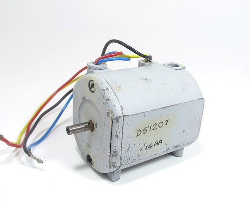
Here's a puzzle for you. Can anyone tell me anything about this motor?
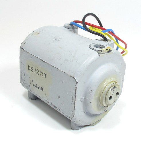
Bought for £1 out of curiosity, it runs very smoothly on 12V DC but would (according to the markings on the end) be happy on 24V. It's very well made with screws over the brushes to allow for adjustment and replacement. I think you can adjust the end float by turning the lump with two holes in at at the back of the shaft. This is painted with a clear glaze, presumably to fix it.
The biggest oddity is that there are pairs of wires to each polarity - red/blue and yellow/black. These are twisted together so I assume they do the same things but why would you want to feed the motor from two places?
Dimensions:
Length over shaft - 75mm
Width over the flat sides - 40mm
Height - 46mm
Shaft diameter - 3mm (it appears hollow too)
A plate on the end says Type CM3. The motor is No. 051207
The seller suggested this might have RAF origins but knew no more.
9 comments:
Not sure about this one.
The numbers and letters marked on the motor don't tell me anything, either.
All I can think is that the 4 wires might suggest something like a servo, or stepper, motor.
I wonder if the second set of wires could be used for sensing how fast the motor is actually turning, i.e. to measure the back EMF.
servos tend only to have three wires, but a stepper motor often has four. Mind you I would have thought pairing up the wires would not work well with a stepper motor, but then again I've never tried that.
One set isn't for the field whilst the other set are for the armature?
If you've had it running at 12V then clearly you've had it connected up Ok, did you need all four wires connected for it to run or not?
I haven't tried it witl just 2 conencted. At the moment the pairs are twisted together.
Will have a play and post results.
It crossed my mind it might be a dual voltage motor, but then wouldn't it have six wires?
Ah, is iot a capacitor fan motor?
If it runs with all four wires connected, then try swapping the polarity of one of the pairs - if it changes direction then I'd suggest one pair are for the field winding, the other pair are for the armature.
If you swap the polarity on both pairs of wires at the same time then the direction will remain unchanged.
Having seperate connections to the windings gives ultimate control of the motor, as they can both be manipulated seperately to acheive different things, alternatively they could be connected together in either "series", "shunt" (or "compound") configurations. Ones to Google for the differences to save me writing pages here!
ps. I'm guessing so far you've had it connected in "shunt" mode if they are connections for the two windings.
I agree, looks like separate field and armature windings, which mean it has no permanent magnets in it.
If you wanted to test, the field windings and armature windings will have quite different resistances. The armature should be low, the field windings should be high resistance.
Post a Comment