More bonnet fun. At the front there is an extra section containing a fan. Nothing too hard here, just a wrapper to run around the front part. The resulting unit isn't a great fit against the main bonnet section but it's close enough. Of course if I hadn't used too much heat to join the two, I wouldn't have unsoldered the wrapper again which made for some slightly frustrating work.
The doors are a single etch and lined up pretty well. All the holes for the handles matched up properly and the top is straight. Attachment is from the back through holes in the formers which makes the job easy - no need to clean up excess solder showing as it's all hidden !
Getting bonnet handles identical is important. Luckily spacing from the door can be handled by a jig/spacer made from a chip fork. Drawing a line on this also makes snipping the resulting item to length, using my best flush cutters, easy and consistent. In smaller scales I end up using bits of card but chip forks are so much sturdier...
Tuesday, June 30, 2009
Monday, June 29, 2009
Bonnet wrangling
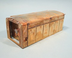
Scary job time - fitting the bonnet top.
This is a large, flat sheet which has to be bent and riveted then soldered over some formers with nothing in the way of positive location assistance.
First up I riveted the sheet. Then it was annealed as best I could using a cooker flame. I'd hoped that this would make the metal malleable but if it did, I couldn't tell the difference. The top bend is easy enough, it's pretty gentle and can be formed around any round object. Pondering the sharp corner though I chickened out and decided to use the formers to make sure everything is in the right place. That sounds sensible but it's risky - pull metal too hard over thin formers and you get sags between ridges.
The top was attached centrally and then the bending started. Most of the work was done with fingers. Eventually though, more brutality was required and I clamped the whole thing upside down in a vice with wood to protect the rivets, and lots of heat and solder pinned the ends of the top to the former sides. Not pretty, not fun (the wood kept catching fire) but it worked.
Sunday, June 28, 2009
9F behind the bar

DOGA AGM time. I packed up my competition entries and headed down to sunny London. After picking up this years bit of card to act as a background for the photos from Housemans bookshop, and then counteracting all that leftie goodness with a McDogBurger, it was off to The Model Railway Club.
Before the meeting proper we had a weathering demo from D&P Models. Watching someone merrily airbrushing acrylics over nice new RTR locos whilst explaining what he was doing and why. In around 20 minutes the models looked a whole lot more realistic and even I'd learnt something, and I've always been happy with my weathering techniques !
Next up the competition judging took place with those present voting on their favorite models in each class. We had a good turn out with 27 different models entered. The quality was very high again.
Finally the official business took around an hour. I was the Chairman's stunt double - he was unable to attend due to collecting his daughter from university in Sheffield. Personally, I think he should have explained that there is a perfectly good railway line from there and then turned up at the AGM but apparently that's because I'm not a soft hearted parent...
The competition results were announced, I managed a second place in the kit built locomotives category. The winner had built a beautiful 0-4-2 using a Jidenco kit and fully deserved his victory. Simply putting one of those together deserves a medal as they don't have the best reputation in the world !
After the even a few of us repaired to the Doric Arch pub at Euston station. Top quality beer as sensible (for London) prices. The walls are decorated with real railway ephemera and behind the bar is a 3 1/2 inch gauge 9F. This is a whole lot more interesting than the farm implements nailed to the walls of most "character" pubs. I wonder if the landlord was a big customer at the nearby Collectors Corner when it was open years ago ?
You can see pictures of the entries to the modelling competition here.
Saturday, June 27, 2009
Express Warflat
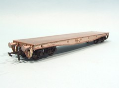 Months ago I rashly promised to build a sample Warflat wagon for the Double O Gauge Association stand at exhibitions. Delivery at the AGT seemed like a good way of saving postage. The AGT is tomorrow and I realised that the wagon was still a flat pack. Some speedy work was called for.
Luckily I've built this model railway goodie before. In fact if you want full instructions, you can visit a photographic build I did a while ago. In that instance I was supplementing the kit instructions as an aid for those who'd never had a go at an etched kit before. This time, time was of the essence and so I could do things the easy way using all my toys.
So out came the mini blowlamp to blow solder around the larger bits and the RSU to stick those fiddly strips of rivets and retaining rings to the side and save me a whole lot of cleaning up. 4 hours later, allowing for a short tea break, and some pretty intense model making, I had the resulting wagon. As it's a sample for the stand I sprayed lacquer over it rather than paint. That way potential buyers can see what they are getting into.
Next time though, I'm going to take my time.
Friday, June 26, 2009
Making steps
 The trouble with looking at prototype locomotive photos is that you find more work. At the front of this Ruston as some nice, inset steps. Entirely different from those provided in the kit. Yippee.
The photos were quite clear on the design, but a hard to work out precise dimensions from. Again, I went for something that looks right compared to the rest of the loco. The buffer beam for example gives a pretty good idea of depth. The width is shown by the spacing between sandbox filler and front. Then all (!) I had t0 do was draw the holes to be cut on some metal. Time was saved by soldering the two sheets of nickel silver together once the vertical fold lines had been scribed heavily with a skrawker.
A bit more cutting and filling later I had a pair of U shapes with step holes. Some more nickel at the bottom with a small lip strengthened it all up. Then the footplate hole was cut and the steps fitted. Ideally I'd have soldered them to the underside and then cut the top but again, the pictures showed the top edge of the steps poking up so I had to replicate this as well.
Hopefully the rest of the model will be similar to the kit. Why can't prototype loco owners leave things alone ?
Thursday, June 25, 2009
Modifying the back
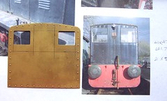
Having learned a lesson with the chassis mods, I have been examining the photos of the Ruston locomotive closely before touching the metal. One of the first changes between the prototype and the kit I spotted was the cab back. At some point during the locomotives life, the windows were enlarged and squared up a bit. This looks more modern and for the driver, would have improved visibility quite a lot.
Luckily the shot of the cab back is pretty square on so with a bit of measuring and scribbled match I could use this to work out the correct sizes for the new windows. With perfect accuracy unlikely without a plan, I have tried to make the proportions as close as possible.
Drilling holes in the corners followed by a bit of work with the piercing saw (2 broken blades) and finishing up with a flat file has resulted in a much better view into the cab. Good job there are shots of the inside so I can detail this a bit.
Wednesday, June 24, 2009
Big rivets
Last time I built the Ruston locomotive kit, I used the traditional hammer and blunt nail technique to form the rivets. While I own the best rivet forming tool in the business, the GW Models press, the supplied anvils only go up to O gauge. In G1 the results are far too small.
Now GW Models do produce a version suitable for the larger scale but it is £150, which is rather a lot for the occasional model. Mind you, like all their products, it is a beautiful piece of kit and worth the cash.
A phone call (no web site here than you, this is a proper traditional engineering company) to the proprietor was instructive. The tools for the G1 rivetter won't fit in the standard one I own. However it might be possible for me to do something myself, he could supply a couple of anvils for a fiver which I could drill out , harden and then try in my machine.
Off went the cheque and few days later the anvils turned up in a jiffy bag complete with some handwritten instructions. Following these I drilled the hole out to 1mm and then hardened the steel by heating it to cherry red and dropping the hot lump in some oil to quench it. Not having done this before, I used a small pot of oil left over from an oil change on my camper van. The big surprise (for me) was the colour change in the metal. It went from a shiny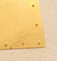 silver steel colour to a shiny black. The same colour as the anvils supplied with the tool in the first place, which I guess means I've done something right.
In use, the tool produces lovely domes in the metal. You have to use the punch intended for forming raw metal rather than the half etch version - that's too sharp and either gives a tiny lump or punches clean through the metal.

Now GW Models do produce a version suitable for the larger scale but it is £150, which is rather a lot for the occasional model. Mind you, like all their products, it is a beautiful piece of kit and worth the cash.
A phone call (no web site here than you, this is a proper traditional engineering company) to the proprietor was instructive. The tools for the G1 rivetter won't fit in the standard one I own. However it might be possible for me to do something myself, he could supply a couple of anvils for a fiver which I could drill out , harden and then try in my machine.
Off went the cheque and few days later the anvils turned up in a jiffy bag complete with some handwritten instructions. Following these I drilled the hole out to 1mm and then hardened the steel by heating it to cherry red and dropping the hot lump in some oil to quench it. Not having done this before, I used a small pot of oil left over from an oil change on my camper van. The big surprise (for me) was the colour change in the metal. It went from a shiny
silver steel colour to a shiny black. The same colour as the anvils supplied with the tool in the first place, which I guess means I've done something right.In use, the tool produces lovely domes in the metal. You have to use the punch intended for forming raw metal rather than the half etch version - that's too sharp and either gives a tiny lump or punches clean through the metal.
Tuesday, June 23, 2009
Gear perving
Will you look at the quality of this gearbox !
Oooooooh, it's loooverly. Thick brass sides encasing high quality, accurately cut gears all beautifully meshed. Even a spiral cut first stage and all mounted on a Portescap motor. I suspect there are mechanism fetishists out there who have drooled all over their keyboard.
And yes, it runs as well as it looks.
For the technical, this is an ABC models gearbox, I think one of their units designed for O gauge as the locomotive is designed around 7mm technology. It's tiny for the space available but unless you want to stuff a washing machine motor in, then that's going to happen in the cavernous interior of the Ruston.
As a test, I put the wheels and mechanicals into the bare chassis and using a slightly flat 9V battery, had it perform a circuit of the garden railway at walking pace. If I'd wanted slower then 3V from a pair of AA batteries was more than enough to turn the wheels.
Monday, June 22, 2009
CDU ?
 Bill asked:
...I've followed ur link from the 3mil e'group to Melbridge Dock and on to 'point motors':
http://philsworkbench.blogspot.com/2009/01/point-motors.html
...Glad I did because it reminded me of reading what you have to say about Peco from a previous reading.
I'm getting reports from a few mates who have trouble with the PL-10/12/13 combo and even on the N gauge point! The complaint is unreliability to the point of no-go which is disappointing to hear. I've asked the question if they are using a CDU and the universal answer is no.
Tell me, was the use of a CDU your solution or did you just start out with a CDU and therefore sailed through these unreliability problems without ever realising there was a storm ahead- if you didn't, as so to speak... or do you feel your experience was down to something else?
I had to think quite long and hard about this and I think the answer dates from the mid 1980's when we built a layout called "The Cawood & Wistow Light Railway", a model of the line of the same name. It used PCB track and PECO motors and for a while the wiring was as per the PECO instructions which didn't include mention of any assistance. The idea was that you just attached the motor to a 16V AC output and used a probe and studs for switching. We had the same problems, points didn't reliably change and often just buzzed when we tried to switch them.
Introducing a CDU into the circuit solved most of these problems and has been part of any layout wiring plan since. That's why I had to ponder as it's so long ago since we tried not using one. For the money (Modelex heavy duty version, £6.95) you can't beat one.
Obviously you do need to check that the points aren't glued up, or have ballast in the blades but if that isn't the problem get a CDU. In fact, get one anyway.
Oh, and if you are using PECO points AND adaptor bases, take the over-centre spring out of the later, the motors aren't strong enough to move two springs and you only need one anyway.
Other peoples hobbies
I took my Dad for a Fathers Day treat to Hillers near Evesham. It's got nice coffee shop with excellent chocolate cake, a fine farm shop with delicious organic produce and a miniature railway. Oh and they were holding a small model engineering show. Well, he doesn't cook but loves the sound and smell of a steam engine...
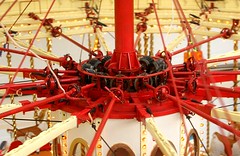
Anyway, we wandered around the displays and were impressed at the workmanship to be seen even in such a tiny are as this. The photo shows the top of a model gallopers which is under construction. I suppose I should have been looking at the pretty horses (I did wonder how you carve so many identical steeds) or the exquisite organ in the centre. Not me, I looked at the gears and mechanism that made the horses go up and down. I've always wondered how these things worked and looking into the works I could see easily. The bevel gears run on a rack and as the carousel rotates it drives these which rotate a rod which the horses are attached to and this moves them up and down. Fascinating.
Well I found it fascination. Stop looking at me like that.
Anyway, we had a ride on the miniature train (fare 70p) which runs in an overlapped figure of 8 for 1/3 of a mile. 7 1/4 and 5 inch gauges can be accommodated. Along the way there are loads of gnomes, waterfalls and wild (plastic) beasts to look at. This is a clever marketing move as kids want to take several rides so they get to see everything. It certainly worked for the children behind us. This might be a particularly British thing, but there is something both daft and fun riding a tiny train behind a little steam engine.
There were static boats and planes to look at. We had a nice chat with the guys from Evesham MBC who had some fine models. The longest talk though was with a pair of miniature traction engine owners. I now have a better idea how to drive one of these and also the work involved in building one. From being the other side of the barrier I know how pleasant it is to meet people who have some idea of the work but ask intelligent questions - you get to show off a little someone who sees lots of well made components rather than just a "pretty" engine. After all those years in the workshop (3-4) getting to bask in the glory of your creation must be a relief. What better way to spend a sunny Sunday ?
Sunday, June 21, 2009
Tractor Day
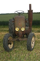
Our railway club is based on a farm. We are surrounded by fields and bucolic Warwickshire scenery. It's handy for the model boat club and on a nice day a lovely place to be.
The farmer, our landlord, collects tractors. Not any old tractors (all farmers do that, mostly rusty, broken ones) but foreign single cylinder ones. He's not alone either, it seems there are plenty of other people out there who collect and restore these machines. And they like to show them off so he organised a weekend get together.
On the Saturday evening there was to be a hog roast and after a little negotiation, the railway club was to be opened up to provide some toilet facilities, it being felt that some of those who wanted to eat might be considered to delicate for the portaloos already laid on. If we had enough people some of the layouts would be operating too as an added attraction. As it was most were run and when people weren't consuming dead pig we had a reasonable sized audience.
Now, I quite like putting on a show for the public as opposed to "proper" modellers. If you've read my reports on shows before (and if not, feel free to catch up on old entries, it should distract you from work for a while) you'll know that I find the early morning session at any model railway exhibition usually presents a crowd that stand around looking grumpy in silence. Later in the day the families start to arrive and they aren't afraid to ask questions and chat for fear of looking stupid.
So, a room full of normal people was chatty and generally very appreciative of the models on display. "Modellers" may see the buildings on one layout as simple card kits - humans look at the effect and are gobsmacked that over 100 houses make up the scene that looks a bit Coronation Street. They also don't get picky about the formation of trains but do get excited about sheep and pigs on hillsides. I suppose the tractor hobby has a higher farmer:townie ratio so they can probably tell us what breed the pig is, we just think it's Priesler.
Of course there has to be one.
Since I'm not attached to a layout, I did a bit of general stewarding. My first job was to use some barriers to prevent access to one corner of the premises which had a couple of layouts not being operated and also workbenches with tools on. I set the barriers so it was easily possible to see the layout and yet protected it from wandering hands. This worked a treat - lots of people enjoyed the model (especially the steam road roller on the bridge) and appreciated the high level of craftsmanship on display. In fact they were less trouble than the average enthusiast at a show.
All except one mother and young daughter, who found a circuitous route around the various obstacles and by the time I got to he were in front of the station forecourt and pointing at the horse drawn vehicles in the scene. Before pointing became touching I politely invited them to return to the correct side of the barrier. Mum huffed, "I only wanted to get her [the daughter] closer to the horses."
And to be fair she had. A whopping 6 inches. They were easily seen from the barrier side but that wasn't good enough. So she taught her daughter a lesson - if you can physically overcome an obstacle then it's OK to ignore it. Find a gap in that fence and it's OK to go through even if the implication of the fence is that you should stay back.
Having returned to the public side she then flounced off to the foyer with child and spent the next few minutes giving me evil looks before dragging the rest of her party (Dad ?) out. Obviously it was me that was in the wrong !
Now you might argue that if we don't want to take the risk then fragile things should not be out on display, but why should this be the case ? The people who build layouts are justifiably proud of thier work and keen to let others see the results of thier labours. If we want to persuade anyone that railway modelling isn't just funny men playing with trains, showing off high quality models seems a good method. Obviously there is a risk and we accept that. I've seen accidents happen and the person who did the damage is usually mortified - it ruins thier day more than the person who ends up with the repair.
Ifyou feel the need to see more farm equipment, you'll be pleased to know there are more photos here. Go on, fill your gumboots !
Or if you just want to watch the trains go by:
Saturday, June 20, 2009
Brummies got rulers !
 Last time I built this locomotive kit, there were a few issues with the frames (too narrow) and the axle bearings (too wide). That's all part of the game as far as test builds go - there will be hiccups and you just fix them or find a workaround, meanwhile the manufacturer will go away and sort the problem out. I know everything should be correct first time out but this is real life and it's not. A good kit will have been put together by someone who isn't the designer of manufacturer. Then fettled. All this before the first buyer gets their hands on it.
Anyway, this time I find an extra fret in the box containing frame spacers that are slightly wider than the ones on the main etch. Put these in and the bearings have to be shaved back a touch to the ends of the axles. This is far better than having to use washers to shim away any sideplay.
Better still, the bearing makers got the middle hole right so I didn't have to bush this either ! You might think that this was an odd error originally but it can be easily explained; G1 axles are fatter than O gauge ones and the bearing makers usually work in the larger scale. The trouble is that the axles are the smaller ones as it somehow helps keep the cost down and results in a 10mm kit that costs no more than a 7mm one. Of course you can still use G1 wheels, for example those machined from iron castings, you just have to ream the hole out a bit more.
It's nice to know that the effort on the test build pays off and ruler manufacturers have had two more sales in the Birmingham area.
Friday, June 19, 2009
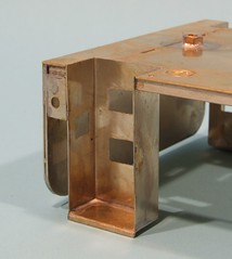
Excess holes
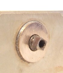
This Ruston locomotive doesn't feature jackshaft drive, which means the chassis has a hole too many under the cab. It seemed sensible to fill this in before starting assembly proper. You can't ignore these things in Gauge One, people notice.
Holding a bit of scrap etch behind the hole I poked a scriber through and drew a circle. In turn, this was cut out with tin snips and filed to fit. Lots of heat, flux and hardly any solder fitted the blanking disks in the hole. Some light filing and polishing with a fibreglass stick left a nice neat job I was pretty proud of.
Then I looked at the prototype pictures properly. These clearly show that the chassis isn't blank in this area on the real thing. In fact there is a slot. A slot with a circular top. The gearbox is obviously pushed into the chassis from the bottom with the drive shaft poking out through the sides. When the loco was converted to conventional drive the slots were simple left in place.
I may have uttered some bad words at this point.
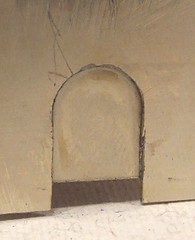 Soooo, I scribed a couple of vertical lines from the bottom go the chassis to the sides of the hole and then cut them with the piercing saw. The blanking disks came out easily enough by wobbling them with small pliers. Then a quick clean up with some files. Finally more spare etch was soldered in the back and the model looked a lot more like the photos.

Holding a bit of scrap etch behind the hole I poked a scriber through and drew a circle. In turn, this was cut out with tin snips and filed to fit. Lots of heat, flux and hardly any solder fitted the blanking disks in the hole. Some light filing and polishing with a fibreglass stick left a nice neat job I was pretty proud of.
Then I looked at the prototype pictures properly. These clearly show that the chassis isn't blank in this area on the real thing. In fact there is a slot. A slot with a circular top. The gearbox is obviously pushed into the chassis from the bottom with the drive shaft poking out through the sides. When the loco was converted to conventional drive the slots were simple left in place.
I may have uttered some bad words at this point.
Soooo, I scribed a couple of vertical lines from the bottom go the chassis to the sides of the hole and then cut them with the piercing saw. The blanking disks came out easily enough by wobbling them with small pliers. Then a quick clean up with some files. Finally more spare etch was soldered in the back and the model looked a lot more like the photos.Thursday, June 18, 2009
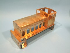
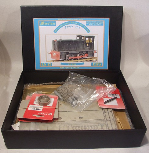
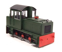
Another Ruston locomotive
Time for some chunky locomotive building. Another gauge 1 Ruston diesel is on the bench. This is the second time I've built this Mercian kit but there are some big differences in the way this model will be assembled from the last time.
As you can see, I am building a model of a prototype. Rich has supplied me with a lot of detail shots so my efforts will be toward building a model of this locomotive rather than simply assembling the kit. The kit itself has been developed in light of my test build as well so some jobs should be easier.
Detail wise, well, the model won't have the jackshaft drive as it wasn't fitted to the prototype loco. Some of the areas that are deliberately sketchy (read: garden and clumsy modeller proof) on the kit will be re-worked to bring the detail level up a bit. I've got some very nice photos of the cab interior and sanding systems for example.
Finally the recommended motorising gear has been eshewed in favour of a very nice super high quality unit which may be the best I've ever put into a model locomotive in any scale.
Wednesday, June 17, 2009
Narrow Gauge Coaches

One pair of narrow gauge coaches - done.
There are some niggles with these kits, which I've passed on to the manufacturer - but at the end of the day a competent modeller with the benefit of a couple of kits worth of experience can make very nice models using the parts supplied.
The sides deserve special mention as I think they are very nice indeed. The pre-rolled roof is a benefit too for the majority who don't have rolling equipment.
Tuesday, June 16, 2009
Roof texture
A brass coach roof is a wonderful thin - strong and easy to fit. It has one disadvantage though, smoothness. Real carriage tops have texture and in the larger scales out models ones should have too.
I've seen the results of sticking tissue paper to the roof and they can be very effective. Trouble is when I try all I get are creases which looks a bit rubbish. On the real thing you aren't aware of the material used, just that it isn't as smooth as the bodywork.
For the NG coaches I tried something new. Each roof was primed in the normal way and then received an extra coat from about 2 feet away. Then, setting the airbrush to a wide spray pattern, several coats of paint went on from the same distance. The plan was that the paint would be partly dry by the time it hit the metal.
The result is like sandpaper. The paint seems pretty well stuck even though it feels like it will bush off. However looking at the models under the light, I could see brass. To cure this, a couple of thinned coats of Humbrol 69 were brushed on. While this took the edge a little off the texture, I liked the results even more.
If you were happy to spend a lot of time with the spray gun, I bet this trick would work a treat to represent roofing felt - varying the paints used would even give the right colours.
Monday, June 15, 2009
Narrow gauge coach bogies

A real three-handed job here. With 4 to build, I was relieved that they didn't all take as long as the first one or it would have taken most of a day to put them together !
First job is to make sure you have the correct stretchers - the kit is available for 14mm (representing a prototypically correct 2 foot guage) and 16.5mm modellers. For some reason I originally got the narrower version which confused me initially although replacements were quickly supplied.
Building started with drilling out the axleboxes to accept brass bearings, plain not top hat ones here so they slide into the hole. Then some dry fitting to ensure the stretchers mate with the sides properly. A locating peg is present but the hole for this has to be drilled out as it's not deep enough.
The one sideframe is soldered to the stretcher. And then adjusted to make sure it is at right angles to the side in all planes. While heating the parts have to be gripped between blocks of wood as the metal warms beyond finger point.
Then the tough stage - gripping the wheels, locating the peg and fixing the other side on. All the while keeping things flat. Much juggling of bits of wood and balancing the assembly on an old computer hard disk. Heating solder on one side for too long also weakens the solder on the other too which just makes the work even more "entertaining".
Any slight un-flatness can be twisted out gently with fingers although I found it easy to over do this and have to twist the chassis back. Frustrating.
Sunday, June 14, 2009
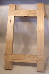
More furniture making
My college course is going well - the frame test piece I started with is now complete. 4 different joints made and all of sort of OK quality. As the tutor said, if I'd been on a City & Guilds course I'd have been told to go and do the whole lot again, but I'm not and on evening classes you get to say that you want to move on. Personally I blame the quality of the wood - I was using a second hand bit from the college wood store and inside it behaved more like balsa than pine when attacked with a chisel.
Anyway, the next project is a small table. First up the challenge was to read the plan and work out a cutting list. Not a big problem as I'm used to plans and picking up the missing dimensions. Then I get handed the wood - a 30ft long 2 inch deep plank. A few minutes with the tools that can kill you hacked enough of of this for my little job and the rest went back into the store.
The wood was quite green with a sticky surface. Once reduced to rough cut parts, most were left for a week to settle. Apparently if you try and work to quickly on anything cut out of a large lump, it can twist or something.
While working a fellow student who is a few weeks ahead of me was trying a machine I'd not seen switch on for a while. Apparently it is a mortiser. For the non woodworker it is a machine that drills square holes.
To use the language of teh interweb: OMG. OMG. OMG !!!
So the next week, one I'd thicknessed all my wood, I asked if I could use the same machine for my mortise holes. "If you really want to" say the tutor as though it wasn't nearly as much fun as making the same holes with chisels. "Yes please" I said - which is short for, "Of course I do ! I've been looking forward to having a go with this bit of kit all week !"
 The mortiser is very clever, if a bit limited, doing only one job in the workshop. The way it works is to have a square tube with chisel sharp ends at the bottom. A course drill pokes out through this and chews away most of the wood. Then the chisels carve away the rest giving a nice square hole with the excess wood being taken away by the flutes of the bit. Simple but very effective. I quickly had some nice clean and accurate slots for the joints. Top stuff.
Incidentally, an evening class attracts a surprisingly wide variety of people. I have wondered if the appearance of an Economics Professor in the group means we should all worry how deep the recession is really going to be...
Anyway, the next project is a small table. First up the challenge was to read the plan and work out a cutting list. Not a big problem as I'm used to plans and picking up the missing dimensions. Then I get handed the wood - a 30ft long 2 inch deep plank. A few minutes with the tools that can kill you hacked enough of of this for my little job and the rest went back into the store.
The wood was quite green with a sticky surface. Once reduced to rough cut parts, most were left for a week to settle. Apparently if you try and work to quickly on anything cut out of a large lump, it can twist or something.
While working a fellow student who is a few weeks ahead of me was trying a machine I'd not seen switch on for a while. Apparently it is a mortiser. For the non woodworker it is a machine that drills square holes.
To use the language of teh interweb: OMG. OMG. OMG !!!
So the next week, one I'd thicknessed all my wood, I asked if I could use the same machine for my mortise holes. "If you really want to" say the tutor as though it wasn't nearly as much fun as making the same holes with chisels. "Yes please" I said - which is short for, "Of course I do ! I've been looking forward to having a go with this bit of kit all week !"
The mortiser is very clever, if a bit limited, doing only one job in the workshop. The way it works is to have a square tube with chisel sharp ends at the bottom. A course drill pokes out through this and chews away most of the wood. Then the chisels carve away the rest giving a nice square hole with the excess wood being taken away by the flutes of the bit. Simple but very effective. I quickly had some nice clean and accurate slots for the joints. Top stuff.Incidentally, an evening class attracts a surprisingly wide variety of people. I have wondered if the appearance of an Economics Professor in the group means we should all worry how deep the recession is really going to be...
Saturday, June 13, 2009
Hornby Magazine Double Whammy
This month's Hornby Magazine is a good one for me - two articles in glorious technicolor.
First: The Melbridge Box Company makes it's debut in print. This starts with a two-page spread showing most of the layout. This is printed several times larger than life size and yet still looks OK. The only thing missing from the piece is a shot of the buildings in a disassembled state, but then you can get this on the layouts web site.
Second: My exciting new series on kit building kicks off. Entertainingly called "Parker's Guides" by the editor, my mission is to persuade people to take up their modelling knives and have a go at something beyond flashing the plastic in the model shop. These builds are exclusive to Hornby Magazine and you won't be seeing them on this blog. First up is a build of a couple of coal wagons, Parkside's French Door mineral and the classic Airfix 16T. Lots of step by step photos and pointers to avoid the worst problems.
Arriving in WH Smiths (other newsagents are available) yesterday I got a nasty shock. For some reason they had buried the magazine on the rack. That and the pile was down to a couple of copies, one of which was well thumbed.
Friday, June 12, 2009
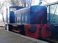
Narrow gauge diesel repainted
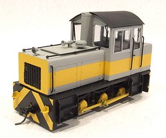 With the paint off and a coat of etching primer on, the repainting process was pretty straightforward. First, a coat of matt yellow went on and when this was properly dry, it was masked off to leave the stripe and buffer beams. Humbrol 64 is a pretty good match for the main colour, as was the primer ironically.
Window frames are silver, carefully brush painted followed by black wipers, handrails and footplate. The spotlight lenses are gunmetal to represent an unlit light.
The stripes on the buffer beams were carefully marked out in pencil and then drawn in with a bow pen. Between these lines I filled in by brush. Then spent ages fiddling to get things properly spaced. I'd have loved to find some transfers but the lifting lugs were in the way. The footplate colour extends up the body slightly and this was easily achieved with the bow pen again.
Finally the whole lot got a shot of satin varnish to unify the sheen's and bring the colours alive.
The chassis painting was all by brush. It worked well so I had no intention of taking it to bits for spraying !
The results look nice. Much better than the green and quite a lot more modern too.
Thursday, June 11, 2009
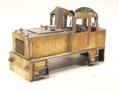
Grit blasting
 I wasn't really happy with the work of the paint stripper so decided to dig out the Badger sand blasting set to see if this could shift the stubborn stuff out of the crevices and difficult to scrape areas on the locomotive. Out came the big compressor and the gun, along with a plastic crate to act as a blasting cabinet.
On when the gloves, dust mask and off I went, blasting most of my supply of aluminium oxide onto the model.
Did it work ? Errr, not really. The brass was affected in a way that will key it and enable to paint to stick well but that paint already on the model stayed pretty much where it was. Occasionally I managed to get a bit of an effect but not often. I'd anticipated blowing the paint off with ease but was constantly frustrated. It might be that my oxide wasn't in the best condition - it isn't a new tub and I'm not sure how often it has been through the gun, perhaps the grain corners have been blown off through being battered against metal model railway engines.
With equipment out I though I'd have a crack at some soda blasting. It's popular in the classic car world as despite being as messy as sandblasting, the mess can be washed away with water and doesn't harm the environment. The action is less harmful to the, metal than the sand version. I loaded the gun with baking soda and tried it out. Result, rubbish. Perhaps the stuff wasn't sharp enough (again) and different brands, especially ones not out of their sell by date, would work better.
Whatever I use, this is a horribly messy job as I don't have acess to a proper blasting cabinet. Even working in a crate I had to keep stopping to brush blasting media off everything, out of my hair and clothes. Don't do it in your best suit is my advice.
Wednesday, June 10, 2009
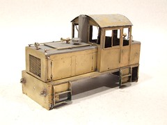
Paint stripping
 After checking the locomotive over, I removed the only plastic items (window glazing) from the body. This allows me to use a "man sized" paint stripper rather than some of that watery stuff that you get for stripping plastic. My choice was Nitromors finest and the model was soon liberally coated in the stuff. For some reason I couldn't help thinking that the stuff looked very much like wallpaper paste. OK, it smells different and you wouldn't want to splash it on the walls but apart from that...
Anyway, after a few minutes the paint reacted and I started working it off with an old toothbrush. The paint seemed to have a good hold and it took a lot of work to get the results you see in the picture. I suspect that there are better strippers out there for this job as your domestic varieties have been neutered to cater for a market stupid enough to stick the stuff up their nose and then moan, "It hurts".
Once dry, a fair bit more of the paint could be picked off with a scalpel blade as the stripper had loosened it from the metal. I spent rather longer on this than expected and then had a better idea.
Nitromors data sheets can be downloaded from here.
Tuesday, June 09, 2009
Narrow Gauge loco repaint
 Paul said to me, "I've got this loco but I don't like the colour. Can you repaint it like the Ffestiniog loco ?"
The model in question is a O16.5 Chivers etched kit for Herlech Castle. It had been put together OK but the green paint didn't make it stand out amongst a thousand other similar models. Mind you, I'd probably have painted it exactly the same colour as green seems to be the British Standard for industrial equipment !
Anyway, a quick web search enabled me to find a nice shot of the prototype engine in its fetching grey with a yellow stripe livery. And wasp strip buffers - rats, I hate doing those.
Anyway, the first job will be to strip the model back to bare metal and then dig out the airbrush for what I hope is a quickie job.

Monday, June 08, 2009
KMBC Open Day 2009
 Down came the rain.
I arrived at the boat club around 9am and was met buy a couple of the other committee members looking bedraggled. We repaired to the clubhouse for a coffee and decision on the rest of the day. The general opinion was that there wasn't much point in hanging on as long as planned. However, expecting a few more people to turn up we erected a new (well, £10 car boot sale bargain) gazebo to keep the rain off those not able to cram into the clubhouse itself.
Gradually more members arrived. Most were a touch wet but still seemed happy. I tested my Slingshot out of sheer bloody mindedness and was followed onto the water by a member of the Footie society . His swing rigged vessel seemed to be able to extract every ounce of propulsion from the meagre wind on the lake. A second boat joined in and from the comfort of our tent we had some sailing !
By 11am Alistair Roach arrived to judge the cork boat competition. He even brought the good weather with him and so after judging (well done for winning the beautiful boat competition Rob) the boats were launched and pottered around the water. When we had a breath of wind they sailed off, most of the time towards the bank admittedly but sail they did.
After this the weather was a bit mixed with odd showers. Enough sunshine allowed some general sailing and a couple of slingshot races. My boat seems to be OK now, clocking up over 16 laps in each race. Quite a lot of water is finding its way inside though, The prop tube can be the only possible source so I'll need to look at greasing the shaft to stop this happening.
By early afternoon lost of us were sailed out. When I left a couple of people enjoyed the sunshine and the chance to get on the water without anyone else around. It just goes to show - even when the weather doesn't want to play ball, all you need is the right group of slightly mad people to have a good time.

Sunday, June 07, 2009
Going green
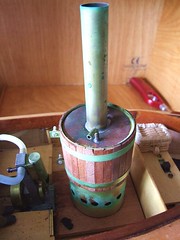
Preparing some model boats for today's sailing, I discovered that the boiler of the fantail launch had gone green !
All the brasswork was covered in a slightly oily verdant substance. Looking at the areas around the air holes I can only assume that this is a residue of the solid fuel camping tablets I use to power the model. Why they should cause this is a mystery - the model has been stored in the dry out of season.
A quick rub with some Brasso wadding had things gleaming again. The a bit of water in the boiler and a touch of heat had the engine turning over like a good 'un. Mind you, if the rain doesn't stop, the boat stays in the box. The open hull will collect more water on top than underneath !
Saturday, June 06, 2009
Slingshot number 9

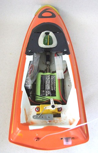
The electrical bits have now been crammed into the Slingshot and it's ready to race. Everything seems to have fitted and works, at least as far as you can tell without putting the boat on the water. It's chucking it down outside so I'm going to take the risk and wait until the race !
Somehow the motor seems to run smoother with the Viper speed control than the original one. I suppose that as this cost 2/3rds the price of the complete boat it ought to ! The tiny unit isn't difficult to hide in the hull either. The receiver was more of a problem, I should have spent a couple more quid and bought a smaller box perhaps. Still, it's sealed up in a plastic bag and stuffed in the side.
The original servo still works the rudder and plugged into the receiver as you would expect. I assume this is a standard unit, just with a moulded yellow plastic box rather than the normal black.
Anyway, it's back together, ready to race. I'll let you know how I got on on Monday !
Friday, June 05, 2009
Greendale Rocket

or
Junk I bought from Car Boot Sales and now don't know what to do with.
For those who weren't children, or owners of children, in the 1980's - or students who spent the day watching television rather than studying - the Glendale Rocket is a feature of the Postman Pat TV series. Apparently it ran between Greedale and Pencaster. The photo shows a model of the locomotive produced as a bit of merchandise to make the BBC richer. I bought it because it looked interesting, nice and only cost me £2.50
My first thought was that this could be converted to run on the garden railway. However with a gauge of 58mm this would be quite a challenge as the garden track is 45mm. In theory a rebuilt chassis could be made but that would push the wheels further under the body which might look odd. Anyway you'd have to dramatically re-work the front end and it would all be far too much hassle.
The loco does give me an idea for a layout though. An idea that if carried out properly, would be a real winner on the model railway exhibition circuit.
How about building an imaginary station which sees trains from popular children's TV series ?
For the minute I suggest we ignore the obvious Thomas the Tank and Underground Ernie stuff. No, I mean classic TV. The proper stuff. Starting with Pat we have the Glendale Rocket and apparently the Pencaster Flyer.
Then we add in Chigley so the line gets Bessie driven by Lord Belborough. Bessie was either painted in two different liveries or there is a second locomotive in the fleet. That gets us 4 engines.
Ivor the Engine takes us to 5. OK, so he only appeared in a cartoon, but I think there is enough detail to make a reasonable model along with Jones the Steam.
Surrounding scenery is easy. A combination of Glendale, Trumpton, Chigley and Camberwick green complete with the characters like Windy Miller and Pugh, Pugh, Barney McGrew, Cuthbert, Dibble and Grubb would be easy enough to do. After all, the real things weren't the most sphisticated models !
Now this sort of model is often the product of the "club clown". He'll hack the models out badly using cheap chassis that don't work very well and plastic kit buildings looking nothing much like the ones in the TV series. To make a really special (and popular) layout, things need to be done properly. That's going to mean a lot of scratch building. Not easy as you'll have to draw the plans up yourself, very few models of the TV models exist and so some skill would be needed to get the proportions right.
Think of it though. What a model. Never mind your P4 perfection, this is what the public want.
Update: Yes, I know, the title of the post should be "Greendale" not Glendale" Rocket. It's fixed now. Sorry to all the Pat fans.
Thursday, June 04, 2009
Model boat wiring
 If I am to go Slingshot racing in Sunday, I need to re-wire the boat. Either that or have yet another day looking at the thing floating pathetically in the lake while everyone else gets to charge around clocking up the laps.
This time I've decided to dispense with most of the electrical bits that came with this model boat and put something reliable in. To this end I've ordered a new receiver and Viper speed controller from Howes
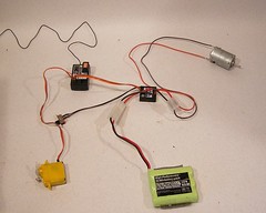
Taking all the gubbins out of the hull, it occurred to me that I could wire everything up and test it on the bench. Which is how I came by this photo which handily shows everything you need to make a radio control model boat go.
Top left you have a receiver. Into this is plugged a crystal (the orange bit indicating the frequency) and the speed control and servo. The aerial is the black wire heading off stage left. This must stay the same length as supplied, so if you attach a whip aerial, the wire must be shortened by the length of this.
Bottom left, the yellow box is the servo. This handles the steering. It's the one that came with the Slingshot - it still works and fits the mountings already.
In the middle is the speed control which (surprise, surprise) controls the speed of the motor (top right). Into this is plugged the battery (green thing bottom right). The switch handles on/off duties. The speed control cleverly incorporates a BEC (Battery Eliminator Circuit) and feeds the receiver with power down the same wires it gets it's control information from.
All I have to do now is connect the motor to the prop shaft and the servo to the rudder, stuff the rest of this lot into the boat and I can go racing.
Wednesday, June 03, 2009
Painting wood and cork
Untreated cork and wood will soak up paint like crazy. The wood will also acquire a furry surface which isn't very nice - and no use to me as a sail !
Two coats of sanding sealer sorted all this out. Thanks to the warm day coat number 1 dried almost instantly and I was quickly sanding it back for the second Go. I'm not sure the cork wouldn't have benefited from more coats than this but decided I'd let the paint do the rest of the sealing.
The orange is Humbrol gloss and the whites Humbrol matt. A couple of coats of each sanded back between each. Mind you, this didn't make a huge amount of difference, the cork is still pretty lumpy. Still, it won't matter once the boat is on the water.
The lines are applied with a bow pen compass as an experiment. The sharp end has been reversed and the now blunt bit runs along the deck. While this worked OK, I think I need to look for a better bit of kit as the pen end isn't particularly good. At least I get to find this out on something relatively unimportant than a prize model locomotive !
Tuesday, June 02, 2009
Unpainted boat
Cutting a cork blog isn't difficult, a razor saw does this very nicely, shaping the result is harder. You can't carve cork in the same way you can a lump of real wood. While the saw helps, I found sawing at the block with a cheap "snap-off" knife with the blade fully extended. This leaves a smooth surface. Think carving the Sunday joint and you get both the methods and an idea of how the waste material comes off. Please don't try slices of cork with Yorkshire pudding though, it's not nutritious and quite chewy.
There's something perverse about sanding a sanding block too. Surprisingly coarse sandpaper works well, the fine stuff doesn't make much of an impression. I didn't go mad on this as this is fun, not finescale.
The sails are very thin play and simply poke into crosses cut in the deck with a knife. The idea is that they can be repositioned depending on the wind direction. Once in the boat actually looks like a sailing vessel. In fact I really like the lines. There is an elegant simplicity about them.
A slot needs to be cut in the base to hold a metal keel and then it's off the the pool for a quick test. On the water Cokyn-Baba is whisked along by the merest breath of wind. Looks good too. Next I think, we need a coat of paint so she stands out on the boat club lake in the rest of the flotilla.

There's something perverse about sanding a sanding block too. Surprisingly coarse sandpaper works well, the fine stuff doesn't make much of an impression. I didn't go mad on this as this is fun, not finescale.
The sails are very thin play and simply poke into crosses cut in the deck with a knife. The idea is that they can be repositioned depending on the wind direction. Once in the boat actually looks
like a sailing vessel. In fact I really like the lines. There is an elegant simplicity about them.A slot needs to be cut in the base to hold a metal keel and then it's off the the pool for a quick test. On the water Cokyn-Baba is whisked along by the merest breath of wind. Looks good too. Next I think, we need a coat of paint so she stands out on the boat club lake in the rest of the flotilla.
Monday, June 01, 2009
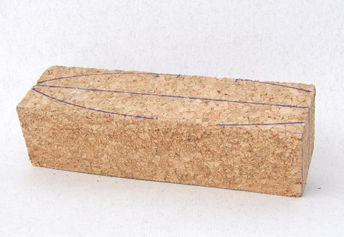
Cokyn-Baba
This Sunday sees the annual KMBC open day. We'll have Slingshot racing (exciting), yacht racing (model sailors praying for the wind to blow), free sailing (anything goes) and a new challenge - cork boat racing.
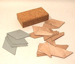
The Cokyn-Baba is a toy boat made from a cork block and powered by think plywood sails. A sheet metal keel keeps the thing upright. Interest has been sparked by an article by Alastair Roach in last Octobers Marine Modelling magazine. He gave a brief history of the models, some instructions, plans and best of all the offer to supply parts for a very reasonable price. Once the competition was announced I sent off for my bits and the photos shows what I got. Marvellous.
Of course I didn't start work immediately, the bits have sat in the pending pile for a few months until I realised the deadline drew near. I also discovered that a number of my colleagues had built their own models and I didn't want to be left out !
Anyway, this should be a nice simple job I thought. The first task was cutting the cork sanding block in half and then shaping it to make a hull. Marking cork isn't as easy as I'd expected - pencil doesn't show up and I ended up using a ballpoint pen. Once I'd carefully marked out the top and cut it my Dad pointed out that he's just drawn his hull shape on a bit of folded card, cut this out and unfolded it to give an automatically symmetrical shape. Obvious really, except to me...
Subscribe to:
Posts (Atom)