Locomotives built from etched kits are normally too light for reliable layout operation. While I like to test them without extra weight (if they work without it, they work even better with it), one of the last jobs before painting is to stick some weight in wherever I can.
The dock tank locomotive is well placed for weighting. The side tanks are nice big boxes which you could fill with lead or any other heavy material (uranium anyone ?). Sheet lead put in during assembly would probably be best but to allow the lightweight testing I decided to drill holes in the bottom and pour "liquid lead" in instead. This is followed by some glue to hold the tiny lead balls in place.
A word on glue - don't use PVA as it can cause the metal to swell. I've seen a 7mm scale GWR 0-4-2 with the smokebox blown apart because it had been liquid lead'd and PVA'd. I've used a cheapo "Liquid Nails" style glue. It is supplied in a tube with a nozzle - which gave me the size for my holes as I used this as a funnel for the lead before forcing the glue in.
Once the glue is in, the holes are covered with masking tape and the loco set the right way up. This should allow everything to dry in the right place. Tiny lead balls find all sort of ways to escape and I know from experience can bung up a model gearbox !
Saturday, January 31, 2009
Friday, January 30, 2009
Squeezing the brakes in
Oh the joys of a reduced size etched kit. I'm sure that the brake shoes and hangers weren't this much of a squeeze to fit in in 7mm scale. Of course the larger scale people aren't using Romford wheels which might be a touch over scale.
As supplied the parts neatly fill the gap available in a complete and short circuit inducing way. Since I've been asked for a running model and not one that will blow every fuse in the house, this needed a little attention. The back of the shoe was filed back the hanger, the front reduced by about 1/2mm and then the shoe re-profiles with a half round needle file.
And did the designer of the prototype have to put front brakes on ? I mean this is fiddly enough as it is without tucking the things behind the cross heads !
Mind you, once all the gear is in place it does look nice.
Railway Magazine 1893
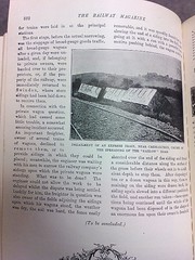
At the model railway club last night I was perusing an old copy of Railway Magazine. In an article discussing whether Brunnels broad gauge, which had recently been converted to standard gauge, was a mistake I found this fascinating section:
Background - on the day of the gauge changeover, broad gauge wagons were to be stopped at a particular time and unloaded. Those belonging to the railway company were sent o the works for conversion or disposal. Any belonging to private concerns were returned to their owners to be dealt with.
In connection with the private wagon question which had caused some little trouble, a somewhat amusing incident occurred. An important freighter, owner of several trains of wagons, declined to remover them or provide sidings in which they could be placed; meanwhile, the engineer was waiting with his men to narrow the company's sidings upon which the private wagons were standing.
What was to be done ? The engineer could not allow the work to be delayed while the dispute was settled. Luckily for him, the freighter in question was also owner of the fields adjoining the sidings on which the wagons stood, the weather was dry, the soil was hard, the fence easily removable, and it was speedily found that by slewing the end of the siding into the field, and going at it with a run with a powerful locomotive pushing behind, the wagons could be shunted over the end of the siding and forced a considerable distance along the surface of the grass before their wheels cut in to a sufficient depth to stop them. After disposing of ten or a dozen wagons in this way, those remaining on the siding were drawn back, the siding slewed into a different position in the field, and another run taken - these operations being continued until the whole of the wagons had been disposed of in the shape of an enormous fan on the owners freehold.
Fantastic. Not sure how it could be modelled though...
Thursday, January 29, 2009
Coal rails
Lots of head scratching here. I know where the coal rails on the locomotive but how I was to get them there was a little more challenging.
As supplied the part has all the strength of thin paper. To give some relief the rails are mostly half etched. I don't understand why as the alternative part is made from whitemetal and the thickness of (scale) tree trunks. Full thickness brass would have been a whole lot easier to handle.
Anyway, I tinned the part to beef it up a little and then used the RSU to attach the back and ends. They seem pretty well fixed but the whole thing is still a bit flimsy. It's position on the back doesn't help as I keep bending them. I know they can be straight but will leave that until spray time to avoid messing up the metal with constant tweaking.
Still, the guards over the back windows look nice, don't they ?
Wednesday, January 28, 2009
Resistance isn't futile
Now I'm onto the detailing stretch on the dock tank I've broken out my resistance soldering unit (RSU). Not a tool I use very often but it comes into its own for this sort of thing.
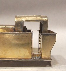
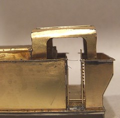
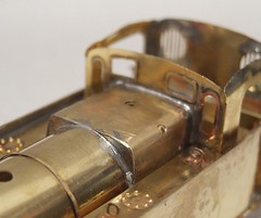
The photo shows a riveted plate and lug fitted to the top of the tank. To use the RSU I tinned the back of each part with the conventional iron, smeared flux on the tank and then holding the part in place with the RSU probe, pushed the foot switch. This makes current flow through the probe and then the part and solder. The solder heats up to melting point. Then I take my foot of the switch while leaving the probe in place. That allows the solder to cool and fix the part.
This is much easier than doing the same thing with a normal iron. This tool has to be removed to take away the heat which means another way of holding the part in place is required.
Best of all, little or no cleaning up of excess solder is required, a blessing around the little bits like this !
Brede back end
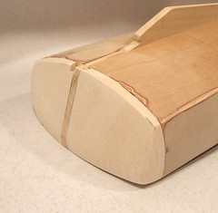
Tradition rules at the back end of the Brede lifeboat hull. Although the keel incorporates some indication of shape I didn't fancy trying to build a framework to support a plywood skin here. No, I went for a couple of solid balsa wood blocks carved to shape.
The basic shaping was carried out with a surform and then finished off with sandpaper on a block.
The biggest problem was working out what shape this area is. I have one vertical in the middle and the plan view shows a slight curve. Apart from this I had to make it up. My result looks OK I think but I'm not confident it is perfect. Let's just hope no one notices.
Tuesday, January 27, 2009
Spraying article in Model Boats
Sometime last year, or possibly even earlier, I gave a talk about spray painting to our model boat club. Seeing an opportunity I wrote most of it down and turned the text into an article which appears in this month's Model Boats Magazine.
Basically I've tried to explain the spray painting basics to absolute beginners. The editor changed my preferred title from "Spray Painting for Dummies" into "Spray Painting for Novices" presumably to avoid legal action from the famous series of books I was aping.
To be honest, reading the text afresh it's a bit staccato and not one of my best, the information is there but it doesn't flow as well as I would like. Still, you do get an exciting bye line picture of me wearing my spray mask !
Roof resolved
Off the roof came and this time the cab back was removed too.
The roof wrapper was still reasonably accurately bent so I just heated up the solder to smooth it out and made a new sub-assembly of roof and back.
Then the cab back was shortened by filing it down to remove the excess 3/4 ish of a mm. I suppose I should talk about careful measurements and highly accurate cutting but to be honest I just kept trying the part on the model until things looked right. Then when all appeared OK I tacked it in position and measured the height back and front with a dial vernier. The numbers came out the same so the joints were made good.
With things still OK the beading around the opening went in. This is a thin strip with a half etch line down the centre to aid location. It's tacked in place and jiggled into perfect position. Finally loads of flux, heat and a tiny amount of solder later it's in. One side needed a little adjustment as all the messing around with the roof had stretched the side a bit. The result, when under paint should (I hope) be invisible.
Monday, January 26, 2009
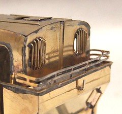
Cab roof
Re-scaling etched railway kits opens up many possibilities. With a few button pushes on a photocopier or CAD package models can be made available in different scales with only a small investment in castings by a manufacturer. Obscure scales rely on this for trade support - many 7mm kits have been shrunk to 3mm which allows those of us in the smaller scale to enjoy a wide variety of locomotives that we otherwise wouldn't have a chance at as we simply wouldn't generate enough sales to justify creating the kit in the first place.
Sadly, just because you can produce something, doesn't mean it is buildable. The parts always scale, the concepts are less reliable.
On the dock tank the cab roof is in 3 sections. According to the instructions you attach the sides and clip the centre part in as required. This way the cab interior is accessible for painting - A Good Thing. In 10 and even 7mm scales I can see this working. 4mm modellers struggle. It's another case of a prototype that doesn't make life easy for a model maker. The roof doesn't have the normal lines and instead is more like a continuous curve. Result; the tops of the sides have to bend in smoothly yet there is little metal to grab hold of to form the curve.
I fiddled with this and eventually gave up. The sides came off the loco and I turned the entire roof and sides into a single part. This was then bent up over screwdriver handles (the bend occurs just above the top of the cab doors gap) with the gentler top bend made with fingers.
All of this means the soldering had to be done from the outside. Lots of flux and tiny amounts of solder were employed to keep cleaning up to a minimum. At this point things were looking good.
 Then I sat back and looked along the loco. Now I appreciate that I'm not completely intimate with every single member of this class of locomotive but I'm pretty confident that none ever visited a custom car shop and had a sporty rake applied to the roof for aerodynamic or style purposes. Certainly the one I'm building didn't. It appears that the cab back is taller than the front by just under 1mm.
Hmmmm.

Sadly, just because you can produce something, doesn't mean it is buildable. The parts always scale, the concepts are less reliable.
On the dock tank the cab roof is in 3 sections. According to the instructions you attach the sides and clip the centre part in as required. This way the cab interior is accessible for painting - A Good Thing. In 10 and even 7mm scales I can see this working. 4mm modellers struggle. It's another case of a prototype that doesn't make life easy for a model maker. The roof doesn't have the normal lines and instead is more like a continuous curve. Result; the tops of the sides have to bend in smoothly yet there is little metal to grab hold of to form the curve.
I fiddled with this and eventually gave up. The sides came off the loco and I turned the entire roof and sides into a single part. This was then bent up over screwdriver handles (the bend occurs just above the top of the cab doors gap) with the gentler top bend made with fingers.
All of this means the soldering had to be done from the outside. Lots of flux and tiny amounts of solder were employed to keep cleaning up to a minimum. At this point things were looking good.
Then I sat back and looked along the loco. Now I appreciate that I'm not completely intimate with every single member of this class of locomotive but I'm pretty confident that none ever visited a custom car shop and had a sporty rake applied to the roof for aerodynamic or style purposes. Certainly the one I'm building didn't. It appears that the cab back is taller than the front by just under 1mm.Hmmmm.
Sunday, January 25, 2009
L&WMRS Open Day 2009
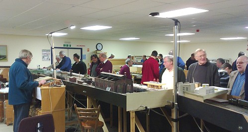
Leamington & Warwick Model Railway Society tradition has it that our exhibition is followed by an open evening. This is simply an attempt to entice more people to swell the ranks of members. No society can ever have too many members - aside from the obvious financial benefit of all those extra subscriptions you never know what extra skills and contacts the new people will bring with them. When we built our clubroom's for example, it was a good job that we had some builders as members !
Anyway we this year we deiced to hold an open day rather than an evening. Our clubrooms are out in the sticks and finding the right turn can be tricky the first time you do it. In the dark it's even harder so a daytime session seemed better. The morning was bright and dry - ideal conditions to temp people out of the house.
My first job was to erect signs from the turn from the road, along the track and to the building. A heavy hammer made knocking the posts in possible if not easy. To be honest once you turn off you can't get lost without driving off tarmac onto a field but you have to cater for everyone if you can so lots of straight ahead signs pointed towards the area designated for car parking in case anyone didn't get the hint from the number of cars parked there.
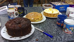
By the time I got back indoors the urn was steaming well, tea brewed and cakes arrived. Lots of cakes. More cakes than kitchen at one point. We always ask members to bring them and this year they did us proud. I'd like to point out I didn't have change to sample any of those in the photo. Nor the chocolate cake that arrived minutes later. Being told that it was delicious was enough for me really...
A few people arrived before we officially opened but we let them in anyway. Through the day there was a steady stream through the doors. Some were from other clubs and just fancies a look around. More expected a free show and weren't disappointed with 4 layouts working well. A very small number, as far as I could tell, actually were interested in joining. Out of the 70 or so who visited a couple signed up on the spot. Others will come back on a normal Thursday night club session to see how we are normally before deciding.
The good thing about the L&WMRS is that you can just come along, drink tea and chat if you want to. Apparently some other clubs dragoon you into a project pretty much as soon as you arrive. That's not our way - after all it's your club and you can make of it what you want.
Even if you missed out, visit the L&WMRS website for more information.
Anyway we this year we deiced to hold an open day rather than an evening. Our clubrooms are out in the sticks and finding the right turn can be tricky the first time you do it. In the dark it's even harder so a daytime session seemed better. The morning was bright and dry - ideal conditions to temp people out of the house.
My first job was to erect signs from the turn from the road, along the track and to the building. A heavy hammer made knocking the posts in possible if not easy. To be honest once you turn off you can't get lost without driving off tarmac onto a field but you have to cater for everyone if you can so lots of straight ahead signs pointed towards the area designated for car parking in case anyone didn't get the hint from the number of cars parked there.
By the time I got back indoors the urn was steaming well, tea brewed and cakes arrived. Lots of cakes. More cakes than kitchen at one point. We always ask members to bring them and this year they did us proud. I'd like to point out I didn't have change to sample any of those in the photo. Nor the chocolate cake that arrived minutes later. Being told that it was delicious was enough for me really...
A few people arrived before we officially opened but we let them in anyway. Through the day there was a steady stream through the doors. Some were from other clubs and just fancies a look around. More expected a free show and weren't disappointed with 4 layouts working well. A very small number, as far as I could tell, actually were interested in joining. Out of the 70 or so who visited a couple signed up on the spot. Others will come back on a normal Thursday night club session to see how we are normally before deciding.
The good thing about the L&WMRS is that you can just come along, drink tea and chat if you want to. Apparently some other clubs dragoon you into a project pretty much as soon as you arrive. That's not our way - after all it's your club and you can make of it what you want.
Even if you missed out, visit the L&WMRS website for more information.
Saturday, January 24, 2009
Clamps
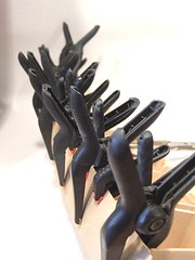
Modelling Rule No. 723: You can never have enough clamps.
On the Brede there are 19 sprung loaded plastic clamps holding the wooden side in place above the chine line. Why 19 ? Because I don't have any more to hand !
For a change I have been lucky. This model boat is a small enough scale that the long nosed clamps will just reach the chine. Much bigger and I'd need to use pins or screw in planking clamps to hold this wood in place. I'd not thought about this in advance but will do in future. I suppose this is the sort of thing that you discover by trial and error normally and call "experience". It certainly explains why some boat building friends prefer smaller scales for scratchbuilding.
Friday, January 23, 2009
Firebox fun
The dock tank locomotive firebox is giving me trouble. My intention was to use the cast whitemetal top supplied. It would have the right bulk, curve properly and add a bit of weight in the right place on the model.
As you can see from the photo, this was not to be. Having bent the casting back to flat and tried it in position there was no chance of fitting the thing. It was narrower than the boiler for a start. I know whitemetal shrinks as it cools but I have a suspicion that this one might be intended for the HO scale version of the kit. Mind you since the instructions don't make any mention of the part, then perhaps its inclusion at all was a packing error.
Aside from the reasons listed above the main factor behind my choice was that I didn't believe the etched firebox would work. It's formed from a half-etched wrapper with little corner pieces. The wrapper was pretty flexible and prone to creasing. The corner bits were tiny and had no locating tabs. All I could do was gip them firmly in some tweezers, heat some solder and poke them into position hoping I got it right.
 First though, the wrapper was bent over a small screwdriver - the bend falls along the line of washout plugs making this work even trickier. Then I started poking hot metal around. The first corner worked well. The second took a couple of goes. Then I fixed in the washout plugs which are on a plate fitted behind the wrapper. And one of the corners fell out.
Much poking and cussing later the part was formed and once trimmed, fitted to the locomotive. I'm now using 100 degree solder as the thought of melting any of the joints doesn't bear thinking about. The results look OK. Not as curvy as I'd like but there isn't enough meat to grasp for filing. Even the small amount I carred out caused a ripple in the top which has had to be filed away.

As you can see from the photo, this was not to be. Having bent the casting back to flat and tried it in position there was no chance of fitting the thing. It was narrower than the boiler for a start. I know whitemetal shrinks as it cools but I have a suspicion that this one might be intended for the HO scale version of the kit. Mind you since the instructions don't make any mention of the part, then perhaps its inclusion at all was a packing error.
Aside from the reasons listed above the main factor behind my choice was that I didn't believe the etched firebox would work. It's formed from a half-etched wrapper with little corner pieces. The wrapper was pretty flexible and prone to creasing. The corner bits were tiny and had no locating tabs. All I could do was gip them firmly in some tweezers, heat some solder and poke them into position hoping I got it right.
First though, the wrapper was bent over a small screwdriver - the bend falls along the line of washout plugs making this work even trickier. Then I started poking hot metal around. The first corner worked well. The second took a couple of goes. Then I fixed in the washout plugs which are on a plate fitted behind the wrapper. And one of the corners fell out.Much poking and cussing later the part was formed and once trimmed, fitted to the locomotive. I'm now using 100 degree solder as the thought of melting any of the joints doesn't bear thinking about. The results look OK. Not as curvy as I'd like but there isn't enough meat to grasp for filing. Even the small amount I carred out caused a ripple in the top which has had to be filed away.
Thursday, January 22, 2009
Underground Ernie chassis
It seems that the Underground Ernie series of the trains based on the TV programme haven't proved to be the cash cow that Bachmann had hoped they would be. The range is being discontinued and the remains sold off for whatever can be realised. Sadly this happened just after people discovered that the "Ernie 1" vehicle had a really useful motor bogie underneath the plastic body.
Most of the stock has been dumped at TK Max stores and lucky people have been acquiring bogies for under 4 quid a pop. Many of these have found their way to eBay.
Birmingham's store didn't have the Ernie (if you have one to flog, let me know as I could use a couple) but it did have the trains themselves for a fiver a set. It's difficult to see in the box but I reasoned that if Bachmann had used standard parts to save money, this had to be a bargain. Since I could only fit 3 sets in my rucksack that's what I got. Each set consists of a powered unit and bogie trailer.
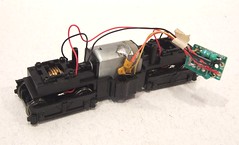
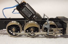
Back home I filled a pot full of screws taking the first unit to pieces. The result is in the photo. The vital statistics are:
Bogie wheelbase: 24mm
Wheel diameter: 10.5mm
Bogie centres: 69mm
The unit has a central motor which drives the gears via a cardan shaft (under 10mm long but easily extendable) that turns a non-swiveling large brass worm. This is coarse enough to drive the swiveling gears built into the bogie. There is a small circuit board attached which I think has a DCC thingy in it - experts would know better but there is an 8 pin board plugged in. All the wheels collect electricity using a split frame system.
Running is smooth and top speed isn't very high - possibly disappointing the kids. Pedants might think that the flanges are deeper than RP25 but no where near the only Lima "pizza cutters". The bogies components are basically the same for powered and unpowered items. One of my units has a broken clip in the power bogie so I'll do some swapping around to fix this properly.
There is an extra mechanism to make the eyes swivel. It's driven off the top of the worm and may well yield some useful gears for other projects.
As raw material for On30 projects this lot is well worth a fiver. Altering the mechanism to OO & HO diesels shouldn't be too hard either. The inner bogie chassis is 12mm over the sides so 14.2 3mm scale would be challenging but not entirely out of the question.
Most of the stock has been dumped at TK Max stores and lucky people have been acquiring bogies for under 4 quid a pop. Many of these have found their way to eBay.
Birmingham's store didn't have the Ernie (if you have one to flog, let me know as I could use a couple) but it did have the trains themselves for a fiver a set. It's difficult to see in the box but I reasoned that if Bachmann had used standard parts to save money, this had to be a bargain. Since I could only fit 3 sets in my rucksack that's what I got. Each set consists of a powered unit and bogie trailer.
Back home I filled a pot full of screws taking the first unit to pieces. The result is in the photo. The vital statistics are:
Bogie wheelbase: 24mm
Wheel diameter: 10.5mm
Bogie centres: 69mm
The unit has a central motor which drives the gears via a cardan shaft (under 10mm long but easily extendable) that turns a non-swiveling large brass worm. This is coarse enough to drive the swiveling gears built into the bogie. There is a small circuit board attached which I think has a DCC thingy in it - experts would know better but there is an 8 pin board plugged in. All the wheels collect electricity using a split frame system.
Running is smooth and top speed isn't very high - possibly disappointing the kids. Pedants might think that the flanges are deeper than RP25 but no where near the only Lima "pizza cutters". The bogies components are basically the same for powered and unpowered items. One of my units has a broken clip in the power bogie so I'll do some swapping around to fix this properly.
There is an extra mechanism to make the eyes swivel. It's driven off the top of the worm and may well yield some useful gears for other projects.
As raw material for On30 projects this lot is well worth a fiver. Altering the mechanism to OO & HO diesels shouldn't be too hard either. The inner bogie chassis is 12mm over the sides so 14.2 3mm scale would be challenging but not entirely out of the question.
Wednesday, January 21, 2009
First skin
My Brede lifeboat has been neglected over the last couple of weeks as model railways have taken precedence. Since the photo of the boat with the stringers in placer is my most popular model shot on Flickr I'm guessing people are interested and better pull my finger out.
With the skeleton in place I have to start covering it up. The plan is to do this with very thin plywood and then fibreglass. I still have no idea if this will work - it should do but maybe not when I'm doing it.
I assume starting at the bottom is the correct thing so hack some cereal box card up to get a part that nearly fits. One surprise is that the bottom edge is flat until the front of the boat. A little thinking would have had me realising that butting up to a flat keel this was bound to be the case...
With the template shape transferred to wood I tentatively tried it in place. All look OK so I ran some aphatic resin along the ribs and started fixing it in place. Clamps hols the chine line and dressmaking pins are pushed through for the top. I'll fill these holes with varnish later so if the boat sinks it won't be these that cause it.
Point motors
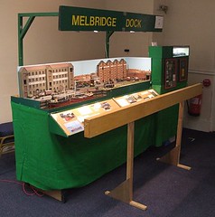
Seeing Melbridge Dock at Leamington show prompted Dave to ask:
Question 1: Why do Melbridges' motors change with an understated "thok" rather than a full fat "thwack!"? Are they standard motors, have you modified something or did the acoustics in the hall hide the noise? I was heartened by their quietness.
The point motors used on the layout are all standard Peco items. In our case PL-10 as that was what was available when the model was built, PL-10E (extended pin version) would be better now. Each motor is fitted to an PL-12 adaptor base which provides locking using an over centre spring (Unlike RTR points, handmade track doesn't provide this. With RTR you actually need to remove the adaptor base spring otherwise the motor isn't always powerful enough) and allows us to screw the whole lot to the bottom of the baseboard. Polarity switching is handled by a PL-13 accessory switch. The pins had to be extended to reach the baseboard top with a brass sleeve hence the preference for the 10E version now.
I suspect the noise reduction is due to a number of factors - the model was seen in a hall full of people which always helps reduce the noise, the 9mm plywood baseboards don't resonate much, the motors get DC not AC (see below) and the adaptor bases aren't screwed tightly to the bottom of it. When testing we've always found that the system works better if the screws are slightly lose unless you can drill the holes exactly in the right place and perpendicular to the surface. Get the screws in slightly at an angle (easy to do when working upside down) and the nylon base is stretched or compressed meaning the slidy bit doesn't move smoothly. How tight the screws need to be is a matter for experimentation.
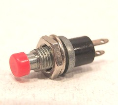
Question 2: What method of switching do you employ? I considered the Peco switches (pretty but difficult to mount on a front fascia), Hornby (show the direction of the point but also hard to fit neatly), stud and probe (don't fancy a dangly thing hanging there) and centre biased "up and down" switches from Modelex, Squires etc.
I am leaning towards the last in this list but wondered what method you employed?
The photo should give you a clue. On the back of the layout we have a track diagram with push switches for each point direction. These are from Squires (PTM190 - P433 in the catalogue) and cost a whopping 30p each. Extra grunt is supplied by a Modelex heavy duty capacitor discharge unit (CDU). This may help with noise reduction as all the power is provided in a burst followed by a lull for a fraction of a second as the unit recharges. Running motors from an AC supply , power flows as long as you hold the switch. AC also causes the motor to buzz slightly unlike the CDU provided jolt of DC.
Whatever you chose, make sure that only a momentary pulse is provided. I suspect Peco switches give this through a clever passing contact arrangement. Sprung toggle switches would do the same but their standard brothers will fry the motor as it can't handle continuous power.
Incidentally, Iain Rice always railed against these cheap switches. In theory they should burn out in use but our experience has been different. The contacts last for many years and some of our have been in use for 20 years.
Finally, if anyone sees the layout at a show, if we aren't busy we'll happily let people have a look under the model to see how it is done.
Question 1: Why do Melbridges' motors change with an understated "thok" rather than a full fat "thwack!"? Are they standard motors, have you modified something or did the acoustics in the hall hide the noise? I was heartened by their quietness.
The point motors used on the layout are all standard Peco items. In our case PL-10 as that was what was available when the model was built, PL-10E (extended pin version) would be better now. Each motor is fitted to an PL-12 adaptor base which provides locking using an over centre spring (Unlike RTR points, handmade track doesn't provide this. With RTR you actually need to remove the adaptor base spring otherwise the motor isn't always powerful enough) and allows us to screw the whole lot to the bottom of the baseboard. Polarity switching is handled by a PL-13 accessory switch. The pins had to be extended to reach the baseboard top with a brass sleeve hence the preference for the 10E version now.
I suspect the noise reduction is due to a number of factors - the model was seen in a hall full of people which always helps reduce the noise, the 9mm plywood baseboards don't resonate much, the motors get DC not AC (see below) and the adaptor bases aren't screwed tightly to the bottom of it. When testing we've always found that the system works better if the screws are slightly lose unless you can drill the holes exactly in the right place and perpendicular to the surface. Get the screws in slightly at an angle (easy to do when working upside down) and the nylon base is stretched or compressed meaning the slidy bit doesn't move smoothly. How tight the screws need to be is a matter for experimentation.
Question 2: What method of switching do you employ? I considered the Peco switches (pretty but difficult to mount on a front fascia), Hornby (show the direction of the point but also hard to fit neatly), stud and probe (don't fancy a dangly thing hanging there) and centre biased "up and down" switches from Modelex, Squires etc.
I am leaning towards the last in this list but wondered what method you employed?
The photo should give you a clue. On the back of the layout we have a track diagram with push switches for each point direction. These are from Squires (PTM190 - P433 in the catalogue) and cost a whopping 30p each. Extra grunt is supplied by a Modelex heavy duty capacitor discharge unit (CDU). This may help with noise reduction as all the power is provided in a burst followed by a lull for a fraction of a second as the unit recharges. Running motors from an AC supply , power flows as long as you hold the switch. AC also causes the motor to buzz slightly unlike the CDU provided jolt of DC.
Whatever you chose, make sure that only a momentary pulse is provided. I suspect Peco switches give this through a clever passing contact arrangement. Sprung toggle switches would do the same but their standard brothers will fry the motor as it can't handle continuous power.
Incidentally, Iain Rice always railed against these cheap switches. In theory they should burn out in use but our experience has been different. The contacts last for many years and some of our have been in use for 20 years.
Finally, if anyone sees the layout at a show, if we aren't busy we'll happily let people have a look under the model to see how it is done.
Tuesday, January 20, 2009
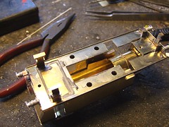
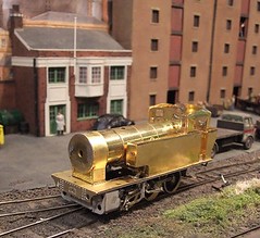
Testing the Dock Tank
There is a difference between running a model on a rolling road and giving it a spin on a real layout. With Melbridge Dock at Leamington Show I took it along to try out. I wanted to be sure that points and badly laid track wern't going to throw up problems.
Result - the thing works very nicely. Slightly better than my model in fact. And it hasn't been run in yet or had any weight put in the tanks. I suppose this is a combination of my greater experience putting chassis together and the jig that helped overcome my incompetence and lined everything up properly first time. It's an expensive toy but for the regular chassis builder a boon.
It was popular too. We showed the unfinished locomotive to many visitors which explaining how the models are built. Perhaps we always ought to keep a part built kit with us when we exhibit.
Monday, January 19, 2009
LWMRS Show 2009 - Day 2
or
BBC Camera Man Smashes Buffer Stop SHOCKA !!!
A two day model railway show will normally see 2/3rds of the visitors arrived on Saturday. Sunday is for people who couldn't make the first day or families apparently. True enthusiasts prefer to fight with the crowds to see things. This means that most of my friends are not true enthusiasts as they all seemed to turn up on the second day. Good thing really as that just meant more chatting and we couldn't have done any more earlier !
Anyway, the weather was fine and many people migrated from the car boot sale to come and see us in addition to those who'd come just for the show. Everyone seemed happy and many were surprised just how much there was on show. There was lots of good stuff on offer but it was wasted on me as I didn't really escape from the back of the layout for most of the day !
Of course things weren't perfect. My campervan decided that three days of perfect running were too much for it and lost the tail light on the drivers side. Trying to fix this on Sunday morning (sadly, it wasn't as simple as a blown bulb) I managed to break the brake lights as well. With the reversing light having been duff for some time I decided to leave well alone and borrow a modern car for the day. Worryingly car we'd never put the layout in to and weren't convinced that it would fit.
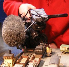
During the afternoon Chris, our exhibition manager, brought round a man in a red fleece who carried a big camera. A bit of lanyard poking out from the neck identified him as from the BBC. The rest showed that ITV sends prettier reporters. Still, the layout was to be filmed and so we attempted to put on a show. Special attention was paid to the brick warehouses as these fall withing the region. I ran a train back and forth several times as it was shot from many different angles. During one of these runs the camera was placed at the end of the model to get an exciting (if badly lit in my opinion) approaching shot.
TV cameras are much lighter than they were in Raymond Baxter's day but still chunky and solid things. Nudging a buffer stop with one caused the wooden beams to separate at one end from the rail built vertical. For 21 years that beam has survived until the Beeb came along. Can I deduct the cost of a brushfull of superglue from my licence fee ?
Anyway, the crowds held up for the day and a few people needed to be shooed out at 4pm so we could knock down. We packed up and found that the layout plus 4 boats fits surprisingly well in the back of a Belingo without any rattles as you drive.
Before leaving a couple of hours lugging things around the hall were needed - it's polite to help traders and layouts move stuff to their vans. After a long weekend and travelling a significant distance it's always appreciated if the locals help with the carrying, something we in the LWMRS have always been happy to do. Squires left with a van quite a bit emptier than he arrived the result of some good sales I'm pleased to say. Last out of the door were Rural Railways who have an incredible and superbly organised system involving huge numbers of banana boxes. Considering these two carry more stock items than anyone else in the show it's not surprising packing up takes longer than most !
By the end of the weekend everyone seemed happy. The show was excellent - it looked good, featured superb layouts and the trade was some of the best at any show. Obvious I'm biased but we've worked hard to get the event this way and the move to the new venue has paid off in terms of quality. If you visited then I hope you enjoyed it. Please send your comments in (good AND bad) via the club website and we'll look at them for next year. If you didn't come then that is your loss. Try harder next year.
In the meantime, I've added more photos to the gallery.
Sunday, January 18, 2009
LWMRS Show 2009 - Day 1
 In a word: Busy.
In two words: Very Busy.
In more detail:
The day started oddly as when we arrived and unloaded the layout it became obvious that the space available was about 2 feet less than we needed. After a check around the hall we worked out that swapping spaces with a trader who hadn't yet arrived would solve the problem. We got enough space to erect the layout, he got a table in the main hall nearer a door suitable for loading.
We set up , wandered around for a short while and then awaited the arrival of the crowds. Situated in the side hall (quite a substantial room on it's own) we expected to have a wait for punters as they usually head toward the second hand stall like a pack of lions approaches a wounded wildebeest. Then they'd find the main hall and then us.
If that was what happened they first people sprinted around pretty fast as we saw then after about 10 minutes. Gradually the crowd grew until by 11am the aisles were pretty full. You could still move but space in front of layouts was at a premium. It stayed that way until mid afternoon with not even a lunchtime lull to dull things.
I met several readers of this blog to whom I say, "Hello and thanks for coming". Nice to know someone reads this stuff. There was plenty of chat all day - we were both hoarse by the end of it.
As well as a dodgy throat I am also knackered so for the time being, please entertain yourself with a set of photos from the show.
Saturday, January 17, 2009
Leamington Show 2009
 Well, it's there. All we need is some visitors.
The venue is huge and once the layouts and traders started to arrive, looked amazing. Much more like a proper show than anything we've done before in a school. Having the space means bigger and better layouts too - even if my favourite is still the tiny "Port Foxdale" !
We have an early start tomorrow. Melbridge Dock is going but couldn't be set up tonight as it's in front of the main loading door for the big hall. So we'll (hopefully) be waiting outside at 8am tomorrow to get in and start playing trains.
See you there !
Friday, January 16, 2009
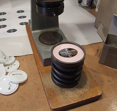
Badge making
This model railway stuff isn't just about building trains or having fun. Sometimes there is real work to do.
The Leamington & Warwick MRS exhibition takes place this weekend. It's our biggest so far y a long way and we need to have an awful lot of things in place on the day. Most of these go unnoticed by the visiting public but are still vital to the success of the event.
One such thing is that all the exhibitors, traders and stewards should be wearing badges to make them easily identifiable. The club has owned a badge making machine for many years and so we are self sufficient in this respect. All I had to do was produce the artwork and then spend a couple of hours pulling the handle on the press to assemble them. The result is a very smart and professional look which enhances the show in a small way.
If you, or your club need 50mm diameter pin badges then get in touch as we are always happy to improve the club finances and help others by providing the service.
Better still, come and see us at Stoneleigh this weekend.
Thursday, January 15, 2009
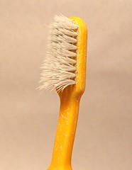
Dental interlude
Yesterday I went to see my dentist, Mr Ubbi, for the annual oral MOT. He's a good dentist, very quick and apparently capable of pain free fillings. The surgery is clean and the equipment looks modern and impressive. Unlike my previous dentist he stick pretty well to appointment times too.
Now no one looks forward to a trip to the dentist but I feel that modellers should receive special compassion for our nervousness. You see we know what the tools look like.
In my toolkit there are a few dental picks, bought from Squires, for digging solder and other muck out of odd corners. They are hard and sharp. When Mr Ubbi attacks my teeth with them I wonder how he doesn't go through the enamel. I fear for my tongue.
Worse is to come if a filling is required. I'm no stranger to the dental bur, a sharp toothed ball of destruction which can eat its way through a whitemetal locomotives insides at a fearsome rate. I also know how hard it is to control. The tools has a mind of its own, often wanting to wander off at speed where it's not wanted. When you listen to the whine of the drill, all I think of is my efforts with similar equipment.
Normal people get to lie there in perfect ignorance. Not us.
And before someone suggests that you can acquire old tools from a friendly dentist I say, "Eughhhh. They've been in peoples mouths !"
Boiler surgery
With the main sections of the locomotive body together, I still faced a challenge. Put simply, bits of it were in the way of the mechanical parts. As usual the hole in the boiler wasn't big enough to allow the motor and gearbox in. Kit designers have to take a guess how much of a gap is required and this varies enormously. Some people will use a tiny motor that barely pokes above the frames at the cost of power. Others will stick in a two-stage 'box that pushes the motor well into the boiler. To make it worse, kits are often intended to be produced in several scales widening the possibilities.
The combination I am using should give plenty of power (this is a working model after all) and a sensible speed range. But it's too big for the supplied hole.
Making space is a horrible task involving a mini drill fitted with a cutting disk to cut across the boiler. Then making the cuts parallel to the sides with anything sharp I could lay my hands on including the slitting disk, scissors and side cutters. The result needs tidying up a bit but at least the body now fits.
Wednesday, January 14, 2009
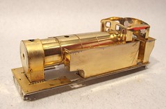
Tanked up
The side tanks are a nice origami exercise in brass. Most of the folds are square and easy to make. The curved area at the front was folded and the first flat area soldered Then the curve is made around a screwdriver and the rest fixed. Since the curve is hidden, absolute perfection isn't required - it's a pity those curves that do require it are often harder to get as good !
The beading along the top is supplied as etched lines with a half etched area to aid location. I found it a little fiddly as I'm not sure the location line is exactly right. Tack soldering and adjusting until you are happy is the key here. Then fix with lots of flux and very little solder, unless you enjoy cleaning off the excess that is.
Finally the tanks are fitted in place. Lots more tacking, measuring and adjusting here. The have to be upright and at 90 degrees to the footplate or the loco will look wrong. Getting this is harder than you'd expect as the eye is often deceived and only a square will do.
At this point the model looks a awful lot like a Jinty. I suppose they came out of the same design office for the same company so that isn't a surprise if you think about it. Standardisation was alive and well before BR discovered it !
Tuesday, January 13, 2009
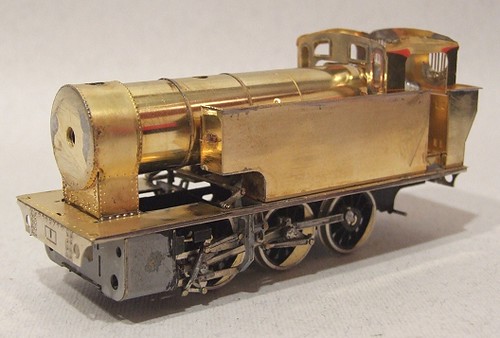
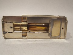
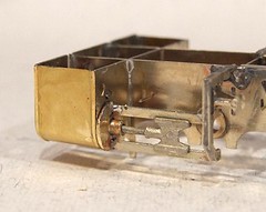
Dock tank boiler
When I built my first dock tank, this was where it all went wrong. Mercian supply the boiler part rolled and in theory all you have to do is solder up the bottom and move on. When I tried it the result was an oval boiler and when I tried to fix this it ended up shaped like a 20p piece. At this point the thing was scrapped and replaced with some brass tube wrapped in plasticard to bring it up to the required diameter - this lead to a replacement firebox and smokebox 'cos you can solder the metal ones to plastic...
Anyway, this time the boiler rolling was finished up in my rolling bar thingies and once soldered is a joy to behold. The front and back supports which form the boxes went on quickly.
The smokebox took me two goes. There's a lot of lamination's to build up the front and I managed to get the wrapper slightly wrong. As it had only been tacked in place a quick heat allowed another go which went much better.
Best of all the boiler top appears to be parallel to the footplate. Always a relief !
Monday, January 12, 2009
Footplate fixed
Attaching model locomotive bodies to chassis is a surprisingly contentious business. Obviously this matters - you want to pick up all the model, not just the top bits - but peoples preferences vary.
Some will argue for a clip fitting at one end and a single bolt at the other. Some prefer a multitude of tiny bolts (unavoidable with US prototypes which don't have a continuous footplate) while others, like me, want something chunky.
The kit is designed to go with the clip and single bolt method. Fine in theory, but the tabs in the footplate don't line up with the slots on the chassis. Altering either is difficult so I have put an extra hole on the chassis and used two decent sized (8BA) bolts. Anything smaller is a pain to fiddle with if you have to undo them. Besides, over engineering is always better than the alternative.
The footplate needs a little alteration before use. It's laminated and the brass top is more accurate than the nickle bottom. As it says in the instructions, the cut-out for the reversing gear needs to be opened up.
Soldering the nuts to the footplate was fun. At all costs you have to avoid fixing the bolt in place. I use combination of CD marker pen and WD40 to try and stop the solder running down the threads. This worked fine with the first bolt and failed on the second. Chopping an 8BA nut and bolt up with wire cutters didn't do them any favours either. I'm glad the third attempt went better.
Sunday, January 11, 2009
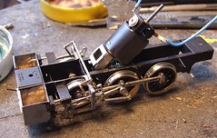
Test running the chassis
Happy days - the dock tank chassis works. Balanced on my rolling road it's thrashing away like a good 'un. I expect that with all the joints in the waggly bits things will be a bit tight and some serious running in will be required. This will also show up any problems - in the middle section of the video the valve rod is moving up and down too much because the reversing link has become detached. Once re-soldered normal service was resumed.
The best news is that with the chassis working I can get on with the body. Our show is next week and I'd like to get enough done so I can test the model properly on a layout.
Saturday, January 10, 2009
Insulated wheels
Looking at this chassis you might think all the hard work is done. The valve gear is attached. It has a motor.
I thought the same. The still photo doesn't show it but when electricity is supplied to the motor all the wheels turn and the rods move around in the expected manner. At this point I was feeling pretty pleased with myself. All that was needed was to fit some pick-ups and track testing could begin.
So I flip the model over and take at look and with horror realise my mistake.
Romford wheels come in two flavours - insulated and uninsulated. The idea is that you put one sort on each side of the chassis so that half the electricity collection is done for you. Add wipers to the backs of the insulated wheels and a running locomotive is the result.
Of course if you mix this up with (say) uninsulated wheels front and back on one side and in the middle on the other then you have a recipe for sparks and short circuits but no movement. It's a beginners mistake that I shouldn't have made but I suppose it just goes to show that we are all fallible, or in my case stupid. There's nothing for it, the middle wheels will have to come out and be swapped over. Happy days.
Friday, January 09, 2009
Walschaerts bits
Time for the fiddly stuff. Once of the features that makes the dock tank special is the Walschaerts valve gear. All that waggly stuff on view makes the locomotive unusual amongst UK shunters - we preferred to hide all that stuff away even if it did make maintenance harder. When I'm operating the layout I love the look of all that moving metal. As a builder my enthusiasm is somewhat dampened.
Having recently build 4 sets for a Garratt this stuff doesn't scare me as much as it has in the past. I'd become used to the technique of using cooking foil to stop solder getting where it shouldn't. I've also started flattening the heads of the pivot pins to improve the appearance. The Garratt was 7mm scale though, the dock tank is 4mm.
I am having some success. The picture shows the return crank to expansion link assembly. There are 10 parts in there (Crank: 2 Rod:3 Expansion link:3 plus 2 pins). The rod is designed to be prototypicaly forked and it fits the link nicely, if you alter the front and back laminations to fit the fork by removing the bottom holes.
One improvement on this loco over my previous effort is that the waggly bits have much less slop in them. Hold the crank horizontal and there is no droop in the attached parts, in fact they are slightly tight so will need a bit of oil and running in.
Thursday, January 08, 2009
Con rod fiddles
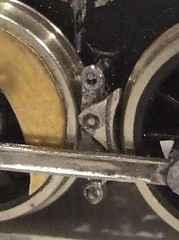
 In his dated, but excellent, book on chassis construction for model railways, Iain Rice ruminates on the problems associated with using Romford wheels. While these are (IMHO) the best wheels on the market - strong, reliable, well engineered and easy to use - the crank throw is generic. Some locos needs something different and there isn't anything you can do about this.
The dock tank is a case in point. I'm not sure what the correct throw is but it's less than that provided by the wheels. For about 1/5th of a revolution the wheels are trying to push the cross heads through the face of the cylinder. To get around this I have had to (on both this model and my original) cheat and turn the holes at the fat end of the con rod into an oval slot. Thus when the crosshead reaches the end of its travel the rest of the movement is taken up at the other end.
Result - the wheels rotate smoothly. The fiddle is largely hidden behind the retaining washer and the rest of the valve gear, To see what I've done you'll need to peer pretty closely. This sort of bodge is why I always say I build "layout locos" rather than glass case models. As far as I am concerned a model should earn its keep so I'll prioritise working mechanicals over looks any day. But then, what looks worse, a stuttering but perfect model or a reasonable one that moves smoothly ?
Now you might say that a different set of wheels would be better and I wouldn't entirely disagree. Trouble is then you are in the realm of plastic centred wheels with round axle holes, home to nightmares of persuading things to stay quartered and the plastic not to deteriorate over time or contact with the wrong sort of fixative. Sorry, give me long term reliability and the possibility of repair without throwing the things away in the future !
Stringers in
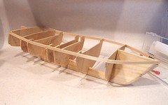
Lots of clamps, pins and alphatic resin later - the stringers are in on both sides. Each is made of two layers of basswood, a method chosen because it's easier to put the front bends in this way than trying to force a single thick strip.
The dust shows I've started to sand the wood to shape and put the chine line in nice and sharp. Basswood (Lime I English I think) is lovely to work and with fine sandpaper takes a smooth finish that is very strokable. At the moment the lines seem to be appearing OK but covering with ply later will show this up better.
I'm still surprised how strong the hull is. I've not had to worry about handling or attacking it with the sanding block.
Wednesday, January 07, 2009
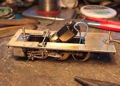
Ready for paint
Decisions, decisions. When building a model locomotive with a full set of waggly bits, when do you reach the point of no return ? How many bits can you stick on the chassis before trapping wheels and impeding the painting process ?
I think this point has been reached on the dock tank. The slide bars are in position, the reversing link supports have been made up and everything is on the face of the cylinders. The next move is to put the wheels back in and start making up the valve gear.
So the metalwork has been thoroughly cleaned with Shinny Sinks and then etch primed. Since the model is to be ex-works a coat of Humbrol Matt black will be brushed on. Then a whole lot of lamination awaits...
Tuesday, January 06, 2009
Top stringer
The bulkheads are now in place. Only a little alteration was require to get them to sit properly - I'd managed to mark out 3mm slots for the keel and then had to amend these to the correct 6mm. Some were a bit deep too but this was obvious the moment the bulkhead was offered up.
Getting the paper patterns off took plenty of padding with a wet cloth followed by scraping and sanding. If anyone knows a better way to fix paper to wood than PVA glue then let me know. My method works OK and I don't want to get into spray glue that remains tacky forever unless I have to.
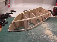
Next up are the stringers. Some 4mm by 1mm bass wood had a bath for a few minutes to make it amazingly flexible. Alphatic resin and lots of clamps (including keel clamps screwed through the wood) hold it in place. The curve of the deck is quite complex which explains why the vac-formed hull didn't really do the job. I'm not sure how well I will do but it's worth a go.
Getting the paper patterns off took plenty of padding with a wet cloth followed by scraping and sanding. If anyone knows a better way to fix paper to wood than PVA glue then let me know. My method works OK and I don't want to get into spray glue that remains tacky forever unless I have to.
Next up are the stringers. Some 4mm by 1mm bass wood had a bath for a few minutes to make it amazingly flexible. Alphatic resin and lots of clamps (including keel clamps screwed through the wood) hold it in place. The curve of the deck is quite complex which explains why the vac-formed hull didn't really do the job. I'm not sure how well I will do but it's worth a go.
Monday, January 05, 2009
Segments
A couple of days ago I pulled a muscle in the small of my back. As long as I don't stay in one position for too long I'm OK but standing is much more comfortable than sitting, something that isn't good news for building etched loco kits.
In the meantime I've been sticking cut out plans to bits of wood for the Brede - something I can do on my worktop and not sitting at the bench.
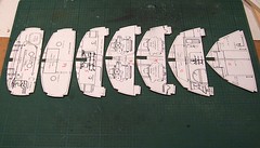
The bulkheads have all be stuck to Lite Ply. This is a wonderful wood used by aeromodellers. As you would guess from the name it is very light. It is also lovely to work as it can be cut easily with a heavy craft knife. I chopped the basic shapes out with a scroll saw but finished to the lines with knife and sandpaper. Experts may be able to work with the saw for the whole job but I'm not practised enough for this.
The keel has been hacked out of 6mm thick basswood. This did need the saw and then a fair bit of sanding but the result looks OK. It's slightly too think for the front of the keel and slightly too narrow for the back. I reckon a bit of tapering with a sander will be enough for me as the fibreglass covering will add a few mm.
In the meantime I've been sticking cut out plans to bits of wood for the Brede - something I can do on my worktop and not sitting at the bench.
The bulkheads have all be stuck to Lite Ply. This is a wonderful wood used by aeromodellers. As you would guess from the name it is very light. It is also lovely to work as it can be cut easily with a heavy craft knife. I chopped the basic shapes out with a scroll saw but finished to the lines with knife and sandpaper. Experts may be able to work with the saw for the whole job but I'm not practised enough for this.
The keel has been hacked out of 6mm thick basswood. This did need the saw and then a fair bit of sanding but the result looks OK. It's slightly too think for the front of the keel and slightly too narrow for the back. I reckon a bit of tapering with a sander will be enough for me as the fibreglass covering will add a few mm.
Slide bars
Not everything included in a model locomotive kit box is as good as you might wish. The cylinder faces supplied weren't the best quality castings I've ever seen. A 'phone call would have had another set in the post but I decided that cutting out a brass disk and sliding some brass tube through it would save me waiting for a delivery. It would also make putting the slide bars together a lot easier - soldering brass near soft alloys isn't my idea of fun.
In the end I scratch built the lot using spare etch for the slide bars. The lost wax brass crossheads supplied aren't as good as Gibson ones would be but they do the job. My method saves a lot of fiddling and I think is more robust - important for a working model loco. Or maybe I'm just awkward.
In the end I scratch built the lot using spare etch for the slide bars. The lost wax brass crossheads supplied aren't as good as Gibson ones would be but they do the job. My method saves a lot of fiddling and I think is more robust - important for a working model loco. Or maybe I'm just awkward.
Sunday, January 04, 2009
Brede plan
20 minutes with a photocopies in Ryman and I had the main parts of the Brede plan down to 1/24th scale. And then I did something sensible (for once) and made a copy of these.
The most important part seems to be the keel and the Brede seems pretty well suited for this. Toward the front there is an obvious line to follow. Likewise the bottom as long as I don't want to model the bowels of the vessel.
To make my life easier the cut lines have been heavily inked in first with ballpoint for accuracy and then over the top in the finest felt tip I had for clarity. Now I need to find some wood to stick it to.
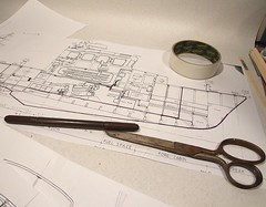
Saturday, January 03, 2009
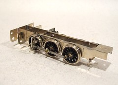
Chassis with wheels
The benefit of using the jig is that I ended up with a chassis that puts all 6 wheels on the ground. 0-6-0 chassis can be problematic if they aren't compensated with the centre axle ending up fractionally lower than the others leading to a see-saw effect. This reduces pickup to a maximum of 4 wheels at a time - you can tell if this is happening by looking at the dirt picked up from the track, if the centre set are muckier than the others then that's the problem.
Pushing the chassis around the wheels rotated without binding. That's not a big surprise as the holes in the rods needed no opening out. I'd have preferred them to be slightly smaller but as things work I won't mess around with them.
The rear supports for the slide bars are in. Each side is made up of 3 laminations and attaches to the side of the frames. The fixing point is tiny so I built up a shoulder of solder to give the joint added strength. After I finished I realised that it would be possible by cutting back the centre layer the sides could be joined with a bit of scrap etch. It's too late to do this now but the result would be a whole lot stronger.
Friday, January 02, 2009
Vic Smeed to the rescue
If I want a Brede lifeboat in anything smaller than 1/12th scale it's obvious I'm going to have to scratchbuild. Slightly scary but at least I can use all the bits I bought to use with the "kit".
Having spent a long while looking at the shape of the boats hull I realised that it isn't that complicated a shape. All it is a hard chine. Digging through my tatty 1989 copy of "Boat Modelling" by Vic Smeed making one from raw materials doesn't look that hard. Basically cut out a keel and some bulkheads and then cover.
Well I have photocopies of the bulkheads and a good side view so it's worth a go.
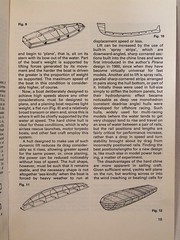
Chassis on jig
The Dock Tank chassis is reasonably conventional. Two sides, a rear spacer and two slot in cylinder ends which space out the front end. Accurate building is essential so I jigged the whole lot up using the con rods to provide the axle spacing.
Each sideframe was reamed to get the bushes to fit and the reamed again to get them to fit when on the jig. I think that one of the rear etched holes is out by about 1/2mm vertically - although this might not be the problem there is certainly something odd going on but it's tiny error. When I built my first model I suspect I just reamed out the holes a lot and did the best I could solving the problem through trial and error. Having an accurate jig helps a lot here and the resulting chassis is square and flat.
One problem I do remember from last time was that the frames are (IMHO) on the thin side. I've always tended towards thicker metal here regardless of scale pretensions. A couple of lengths of L-shaped brass beefed up the top. Previously I used some diagonals across the gap which worked but had to be removed to fit wheels and motor. This time the strengthening can stay in forever although I expect to have the thin the lip a touch when squeezing the gearbox in.
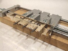
Thursday, January 01, 2009
Now we are three
 Today, Phil's Workbench celebrates it's third birthday. Since I'm still posting, that makes it positively venerable in a blogsphere full of sites that were abandoned after a couple of posts once the writer had discovered that coming up with something interesting on a regular basis.
Talking of posts, this has been a bumper year with over 400 exciting and interesting (hopefully) things to read. There have been too many models built to list individually but I am particularly proud of the O gauge Garratt and Steam Launch. Everything else, even the failures, has been at the very least constructive and a learning experience - for me at least !
Of course this year has been a bit different from previous ones. In the spring I decided to take a career break. Or chuck my job in if you prefer. My plan involved a fair bit of travelling which thanks to petrol prices going through the roof and the campervan deciding to be poorly didn't really happen. What little that did occur can be read about on my travelling blog. To partly compensate for my lack of income I have done a reasonable amount of writing for model magazines and built the odd locomotive for other people. Obviously neither is a full time or even particularly lucrative proposition so during the year my output will diminish again once I get a proper job and stop goofing around !
Anyway, the upcoming year promises more of the same. Another Garratt, some scratchbuilding. A lifeboat or possibly even two. Plus other stuff that even I don't know about. Maybe the pile of kits awaiting building will go down faster than it goes up...
Finally, thanks for reading this stuff. According to my visit counter the blog averages just under 50 readers per day. In the last few months the numbers coming back on a regular basis has "soared" into double figures. Special thanks to those who have linked to me from their own blogs and websites it's always appreciated guys.
Subscribe to:
Posts (Atom)