A daily updated blog typed by someone with painty hands, oil under his fingernails and the smell of solder in his nostrils who likes making all sort of models and miniatures. And fixing things.
Showing posts with label C15. Show all posts
Tuesday, May 13, 2014
C15 in the RM
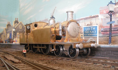
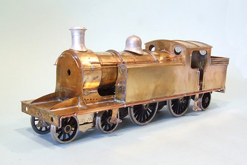
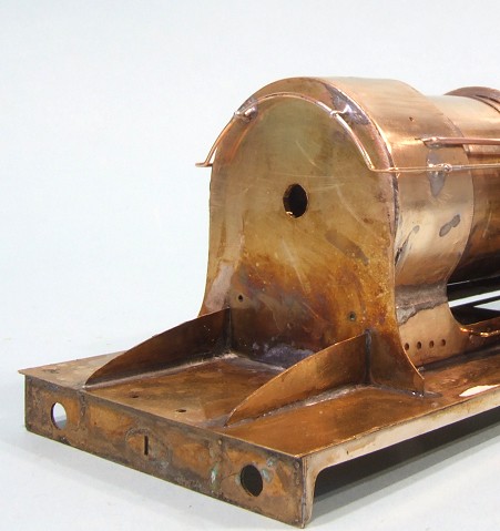
Quite some time ago, I built a Connoisseur Kit for a C15 4-4-2 locomotive.
As a freelancers, I wasn't going to pass up the opportunity to see the build in print so a piece was submitted to the Railway Modeller and after a bit of a wait, you can now read it in the June issue that has just appeared.
Sadly the gentleman I built the loco for, John, passed away a few months ago and so never saw his locomotive on the page, but he did have time to enjoy running it on his layout, which is far more important.
You might be surprised to see me in RM, but the first rule of writing is to write for your audience. The Modeller probably covers a more esoteric range of subjects than other mags and when I wrote it, this article seemed a better fit here than elsewhere. That's not a criticism - far from it. The strength of the model railway press is that all the publications have different characters so you can pick the one, or ones, that suit you as a reader.
In this case, the editor has prefaced my piece with a prototype article which produces an excellent combination and results in satisfying package, even if, like most people, you aren't about to order up a kit and fire up the soldering iron.
Thursday, November 10, 2011
ex-LNER Class C15 locomotive

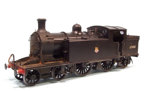
Finally, after rather longer than it should have taken, the C15 locomotive is finished and has been passed on to its new owner. After final assembly and a little light weathering, it looks rather nice. It's ABC gearbox makes it move like a Rolls-Royce too.
I didn't go to town on the dirt. This is a well-cared for locomotive which is doesn't gleam but at the front there is dirt and a bit of rust. The underframes are grey and brown with a bit of earth colour blown on with the airbrush. This creeps up the bodysides a bit as would happen in the real world. Along the top is two shades of black and a touch of gunmetal for sparkle.
On delivery, I found the bogie spring needed quite a bit of adjustment to keep the driving wheels in proper contact with the track. It might be that the spring needs to be shortened, but it can't be left out altogether as the bogie will leap around if some of the weight of the loco isn't transfered to it. I put some lead in the body but as a DCC chip was to be fitted, I left plenty of space for this since I had no idea how big it was ! With the chip in, John is filling the boiler with lead and this should provide loads of tractive effort.
Hopefully the model should be running on the L&WMRS layout Kimble at Warley. With 4 or 5 coaches on the back it should look lovely.
The kit is still available from Connoisseur Models.
Wednesday, November 09, 2011
Coaling up
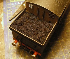
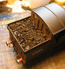
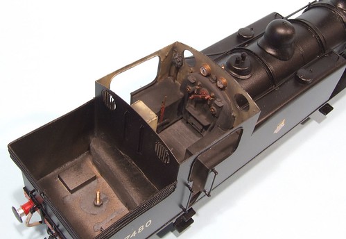
At the back of a tank loco is space for coal. On the C15, it's a gaping hole that could swallow a couple of full-sized lumps of the stuff. I'm not depleting my supplies of real Welsh Steam Coal (honestly, it's what I use, get in touch if you'd be interested in buying some) that much, so I filled the hole with foam rubber filched from some packing suitably chopped about to look like the coal is sloping toward the bunker whole. Somewhere I have some dense dark grey but couldn't find it so this time it was a medium density powder blue. Never mind, a coat of Humbrol black acrylic sorted this out although it looks a lot like "liquid lead" in the photo, the filling weighs nothing.
This was topped with broken up coal stuck in place with lashings of watered down PVA. A 50/50 mix of water and glue plus a drop of washing up liquid to reduce the surface tension. The water came from the pot I cleaned the acrylic brush in so it was nicely black. I'm hoping this adds extra shadows or something. Well, it seemed like a good idea at the time.As well as saving coal, this has the added advantage of not adding a load of unwanted weight at the back of the engine. I'm nearly done and don't want to be re-balancing a model see-sawing on it's drivers.
Tuesday, November 08, 2011
Electric pony
Will 4 wheels on a model locomotive provide enough pickups ? I don't think so and with another 6 to choose from on the C15, I ought to be able to do better.At the front, the bogie is attached to the body rather than the chassis. If I try and wire that up there will need to be provision for the chassis to come out and disconnect. Maybe something involving micro plugs and sockets or very long wires might work but both seems a lot of trouble. Fitting invisible pickups on the thing would be a challenge too.
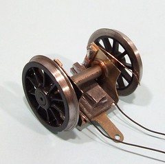
The pony truck at the back looked a better option. It's bolted to the chassis and flops around so will stay on the rails nicely. I added a load of lead to the nickel silver - not that easy as you have to put the cutouts in to access the chassis retaining bolts - to improve road-holding.
Electric collection comes from a couple of PCB off-cuts with phosphor-bronze wires. These have the added advantage of providing some side-springing to the keep the axle centred in the narrow truck.
So now 6 of the 10 wheels are doing something useful. Let's hope this is enough.
Monday, November 07, 2011
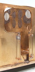
Inside the cab
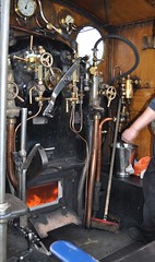
Cab interiors on preserved engines are lovely shiny places. Because the footplate crew are volunteers, a bit of elbow grease and Brasso isn't a problem. Indeed, they are so chuffed to be there and allowed to be in charge of a real life locomotive, that they want to show their steed off to the public and make sure it looks it's best. The cab of 828 is a good case in point. You can see your face, or any other part of your body you care to examine, in the pipework. The cab sides are clean and you can easily see that they are painted with a woodgrain effect. Even the backhead has had attention.
In real life, things weren't so tidy. Crews might have been a little house-proud when they were assigned to a single engine but once you were rota'd on to anything that moved, the impetus to spruce it up wasn't really there. The next guy on the footplate might benefit but you could spend your life polishing and by the time you saw your engine again, the work would have been undone.
On the C15, I wanted to show a working engine. It's not decrepit but the cab is a dirty, dusty place. The sort of effect you'd get by shovelling a few tons of coal from one end of your living room to the other.
After a little discussion on a forum, it was decided the the cab sides would probably be painted beige/cream above waist height. Left on it's own, this would be too bright but a wash or two of dirty black toned it down and gave a pleasantly uneven finish. Once the paint had dried but not hardened, I brushed several colours of weathering powders and some black powder paint around to make things even dirtier and properly gritty. It's not clean but not horribly dirty either. Hopefully more real engine than museum piece.
Labels:
C15,
model railway,
painting,
Prototype Pictures - Railway
Friday, November 04, 2011
Fantastic Mr Fox
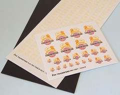
Sometimes I am to forward planning, what Archimedes was to ventriloquism. That's why a few days ago I was looking through my folder of transfers (decals to US readers) and realised with surprise that there were no BR numbers suitable for an O gauge model steam locomotive. Some of the largest BR crest from a OO sheet would be fine, but no digits.A quick telephone call to Fox Transfers found me talking to a very well-informed lady. She could supply me with a sheet full of a specific size crest, or a mixed sheet. I went for the later as I recon there might be some G1 projects that could use the larger sizes. And I didn't know exactly how big I wanted so this kept my options open.
Numbers can also be sent in mixed or single sizes. I knew, thanks to the instructions, I wanted 8 inch and so opted for a one size sheet. I was then promised that they would be sent out as quickly as possible.
As quickly as possible turned out to mean a long envelope arriving in the post the next day. My transfers were packed with a sheet of black plasticard to stop the GPO folding them in transit. Everything arrived in perfect condition.
The crests are interesting. The loco was requested to be supplied with early BR versions. This means the "Lion on a unicycle" version. More importantly, for really early crests, I'll be using the version where on both sides of the loco, the ferret faces the smokebox. Originally this was the plan but when the Royal Heraldry people told BR that this counted as two different designs, presumably requiring two different registration fees, the railway company decided on a single version which faced the front or back of the loco depending on the side it was applied. I quite like the anomaly though and it's a conversation point for those looking at the model.
Thursday, November 03, 2011
Westinghouse pumps
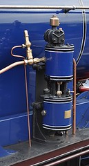
Attached to the C15 smokebox side is a Westinghouse pump, a common feature amoungst Highland engines. The kit makes provides a couple of whitemetal castings and some rough instruction for fitting. Not being familiar with this fitting I looked at photos and concluded that they were bracketed to the appropriate bit of engine and most importantly, held vertically in all directions. If you just fit the bits then the pump will lean as the smokebox at this point isn't vertical.
Making up a spacer from spare etch wasn't too difficult but I still didn't have much guidance on the plumbing. In the instructions there is a side view but it doesn't make it clear where the top pipe goes in. I took it around the back of the disk on the top of the pump which is probably correct, although having seen a real Westinghouse, I'm not so sure now !
Wednesday, November 02, 2011
Pipes and wire
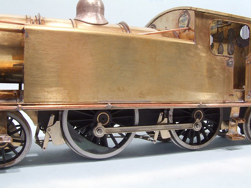
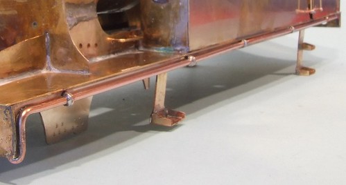
Back at the C15 locomotive, I've been fitting the pipework that runs along the side of the boiler. There's quite a lot of it and working out where it should go has been a problem. Put simply, the pipes emerge from the cab front and end up in the smokebox. The route they take is the issue.Looking at the prototype photos it appears that no two locos are the same. It's possible that they even changed during the live of the engine. The basic route is the same but fitting seems to have been a pretty ad-hoc thing with many variations on the bends in the pipe. Some look suspiciously like the pipe hasn't seen a proper pipe bender. Most don't do anything for the clean lines of the engine, especially the larger pipe which runs at all sorts of funny angles when it leaves the cab.
On the model, all this is produced using various thicknesses of wire. I always use stuff supplied straight rather than rolled - this job is hard enough as it is without acting like a brass snake charmer !
Another issue is fixing the pipes/wire to the boiler. If there are clips, and I assume there are, then these are tiny and not visible in pictures. I just soldered the wire wherever I could secure it and hope no one notices.
Saturday, October 22, 2011
Confessional handrail
A first for me with the C15 locomotive kit is a section in the instructions titled "About this kit - the confessional" where the manufacturer points out all the minor cock-ups in the model that might trip up builders.Mostly these are things to watch out for to make the build easier but at the back of the model there is a mention of the rear handrail. There aren't any holes, you have to drill them yourself. It seems that there is a discrepancy between the GA drawings and photos. According to the former, there is no handrail or step. The photos show a handrail but no step. Another drawing shows both.
Measurements are provided for the holes and since a rear handrail seems logical I've drilled them . Getting these in the right place requires careful work with the ruler and then a drill. Making holes in brass isn't that easy - the bit tends to skid on the surface before digging in. Engineers would use a centre pop to make a depressing to locate the drill in. Belting things with a hammer is a bit vicious on the thin brass but pushing a sharp scriber (a good nail would do) into the location of the hole gives enough location to do the job.
The handrail is brass with split pins acting as handrail knobs. Lots of flux and solder applied from the inside means these will look OK, although my preference if funds permit, is to use proper turned knobs. Mind you, once the thing is painted and on the layout, I doubt anyone will notice.
Thursday, October 20, 2011
7mm Kadee couplings

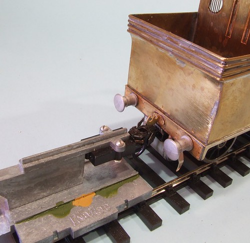
I've fitted a few Kadee couplings in my time, but never to O gauge stock. However, the model railway that the C15 is destined for is all Kadee'd so it needs hooks. John supplied me with suitable couplings and lent me his height gauge and a wagon. I just had to work out how to attach the things to his loco.
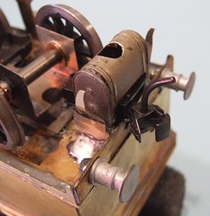
At the back matters were complicated by the air cylinder and the decision to hack the back end of the chassis off. I started by shortening the off-cut so the bogie could swing freely. After a little measuring it became apparent that the draft box could be bolted to a plate fitted to the bottom of the chassis part, which was then attached to the body. One compromise required was the soldering up of the coupling hook - the loco retains these so it can be used on more conventional layouts - as the spring would get in the way of the fixings.
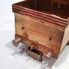
With the parts re-assembled and check for height, I chopped a big hole in the tank and fitted it. We had agreed that it was essential for the look of the locos back end but that it would need to re-locate against the buffer beam, a move of just under 4mm, to keep it out of the way. Not too bad a compromise if the model will be happy on the layout. A hole in the curved part of the tank allows access to the retaining bolt.
At the front a simple L-shaped bracket supports the draft box but I found a different problem. The front bogie axle rubs on the box and lifts the loco wheels off the track. With a piercing saw I removed the cover and this seems to have sorted things. I suspect a touch of glue to hold the spring that centres the coupling might be a good idea though as I've already lost one (John let me have spares of those as well since he suspect I might need them) and we don't want to pepper the layout with coils of wire do we ?
Friday, October 07, 2011
Big time chassis modification

Finescale modellers should look away now. If you want a long wheelbase chassis to traverse a 7ft diameter curve, this is the sort of work that has to be carried out on the chassis.
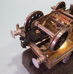
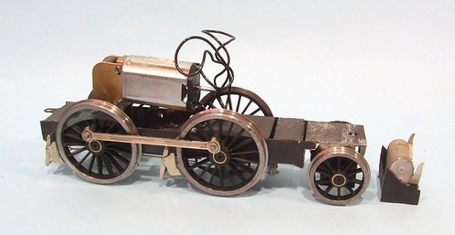
The driven wheels are fine. No problems there. These start when we want to get the radial truck to swivel, or rather, swivel enough to stay on the track. The chassis as designed uses a pony truck within the frame sides to replicate what can otherwise be a complicated item to build. I suspect that the designer hadn't envisaged such tight curves, although he did narrow the frames a bit at this point to assist. Not everyone can build a model where the track is very nearly straight after all !
Anyway, it wasn't enough for the home this locomotive will be heading to so more drastic work was required. The frames have been chopped where the pony truck starts using a piercing saw to just leave the flat part that screws to the body. Behind the pony, everything has been removed and will be mounted on the body after suitable modification to keep it out of the way and let me insert a draft box into that tank.
Back on the layout, the mods worked well. Apart from one area of fiddle yard, the loco trundled around happily and the problem area was most likely a track issue rather than a rolling stock one.
Thursday, October 06, 2011
The C15 takes to the layout

I don't have an O gauge model railway layout. Once upon a time I planned to build one but it got as far as baseboards and then stopped. While this isn't a problem most of the time, when I have a 7mm scale locomotive to test, I don't have anywhere to do this.
Not to worry, the guy I'm building the C15 for only lives 12 miles away. Or 19 if I get lost on the country lanes.
So, off I toddle to try the loco on Leith. I've seen the layout before. It's U-shaped around three sides of a small room. As befits a station, there is quite a bit of pointwork to tangle with and since the room is small, the curve at the end is tight. Tighter than the loco could deal with as it turns out. This thing has a long wheelbase and while I allowed enough swing at the front, the fake radial truck at the back can't move enough and keeps flopping off the track.
Less of a worry is that I've wired up the model back to front. It's too light too, some serious lead in the tanks looks like a good plan. And I've got to fit it with Kadee couplings, which will be interesting.
Monday, September 26, 2011
Making loco wheel balance weights

Not being happy with the supplied C15 locomotive balance weights, I decided to have a go at making them myself. This being a 7mm scale model, I didn't think the result would be too fiddly to handle, in fact I reckoned I might make a reasonable job of it.
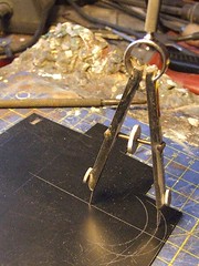
My material of choice was thin black plasticard and the plan was to use the old set of compasses with two points to scribe the curves. I've found in the past that if you scribe them back and forth, the plasticard can be snapped along the lines without any further cutting.
The outer line was easy - measuring the outside diameter of the spoked section gave me this. The inner curve is larger but by an amount I couldn't work out. If anyone knows the match for this, please enlighten me but with a method suitable for someone who only scrapped an "O" level in the subject.
In the end I used good, old fashioned trial and error. After a few goes I got something that was about the same depth as the etched weight and carved the moon-shaped out of the plastic. These were then stuck in place using superglue.The glue seemed to affect the plastic a little, probably because I used quite a lot to build up the depth. A little green filler and some smoothing down soon sorted this though.
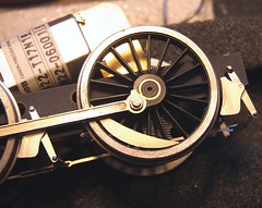
Once problem I did have was working out how far around the wheel the weights should be fitted. The photos appear to show the centre matching the crank-pin sometimes and other being slightly offset. I went with the former but if someone can prove me wrong then I might be up for modifying them.
Friday, September 23, 2011
Brakes and balance weights
Taking a break from narrow gauge matters, I've been back working on the C15 engine. Maybe I'm missing the smell of burning flux !Assembling the brakes is simple enough, there is a hanger into which a shoe is soldered. Since both parts are etched in nickel silver, tinning the parts, holding them together and then heating the lot worked well with nice clean results.
Attaching them to the loco itself was carried out using an acid free flux as I can't stick the chassis in the sink to clean it off. Once hung, the rigging goes on underneath and all seems to fit very nicely. It doesn't seem to align very well with the handbrake lever but I suppose you can't really see under the loco so this won't be a real problem.
What is a problem is that the balance weights don't seem to fit the wheels very well, The curve on their outermost edge and the inner curve of the wheel don't match and just like when I travel on a tube train, I certainly do Mind the Gap.
Friday, June 03, 2011
C15 up on its wheels

A big moment this. Normally I'd have a model engine up on its wheels very early in the build process. With this kit however, this is a little trickier than normal.
The front end of the chassis, the part of the frames that carry the bogie, are part of the body. This means fitting them provides an annoying lump up the front end while you are trying to work above the footplate. Therefore I simply left them off until the last minute. That way, I can work with a model that will sit flat on the workbench and not rock around all over the place. I need all the help I can get after all.
Anyway, the big bits and even some of the small bits, are complete so I added the front frames and screwed the bogie into place. Finally, I get an idea what the finished model is going to look like. To enhance the effect I plopped the chimney and dome in place as well. Obviously I will sit them down rather better than this later on...
Thursday, June 02, 2011
Chuffed by steam pipe

Along the footplate of the C15 tank engine, there is a steam pipe. The instructions suggest making it from a length of 1.2mm diameter wire. There is also some mention of cotter pins to represent the clips that on the prototype, would hold it in place.
I identified the wire, cut it to length and then looked at the clips. While I have some split pins that would do the job, I fancied that a method used for 4mm scale downpipes would work on this 7mm scale model locomotive.
Where there should be a clip, a length of 5 amp fuse wire is wrapped twice around the "pipe"and the tail at the back twisted tight. Then this is flooded with solder and the tail removed - on the downpipe it would go through a hole drilled in the building - and the back filed flat.
A few spots of heat from the RSU and it's a nice neat job. The pipe really is held in place by the clips, just not quite in the same way as in real life.
Wednesday, May 18, 2011
Boiler front handrails

Three goes. Two failed attempts to form these b****y things !
Normally I bend the wire for the front handrails around a convenient pot but nothing to hand seemed to be right. Working with just fingers resulted in a 20p piece shaped bit of rod - several straight bits joined by sharp corners.
In the end I used my rolling bars. Not easy because the stupid wire kept wanting to lie at 90 degrees to the way I wanted it. Even getting the last piece right took many attempts and much frustration.. The some bends to get around the boiler and I slipped the split pins that act as handrail knobs in place.
Everything was tack soldered in place and then adjusted again and again until I was happy. One hint, when read for the final fix, plenty of flux and a small gas flame make for a reasonably neat job which doesn't need much cleaning up. An old lolly stick can be converted to a handy spacer to keep them all out the same distance from the body too.
Tuesday, May 17, 2011
Cab doorway beading
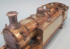
With the big lumps of the C15 together, it's time to start detailing this model locomotive. For no particularly good reason, I started at the cab door.The beading around the edge is supplied as 4 strips (2 for each side) which have a half-etched line along the middle. Simply line up the groove with the side of the opening, tack it in place and pus the metal around the inside of the hole.
I never bother with too much pre-forming, preferring a tiny bit of brute force to shove the metal where it is supposed to go. This works most of the time, especially on larger models. Solder inside the cab as you go and it will be fine.
On smaller stuff I'm normally tempted to leave beading off as being too fiddly to bother with. Maybe 4mm models justify it but in 3mm - well the etched parts are usually too small to use properly. If it's straight, fuse wire works well but to be honest, do it wrong and it looks rubbish. Better to ignore it for an easy life.
Monday, May 16, 2011
Boiler bands, braces and loving the RSU

Boiler bands on model locomotives - a good or a bad thing ?
In real life they are impossibly thing and many prefer to represent them with sticky tape or even a good coat of paint. Kitmakers like to give you some etched strip though, even if it is nearly as thick as the prototype.
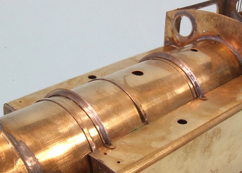
The C15 kit has bands and half etched grooves to fix them in to. Normally I struggle to fit them neatly but that's because I'm too lazy to get out the Resistance Soldering Unit (RSU). When I do, remembering to tin the back of the bands, fitting is a breeze. Slosh the flux around and spot the metal in place with the probes. The heat is localised so I don't have to heat the entire boiler up just to get the solder running on the back of the strip. So tidy is this methods that I was able to fix that band shown lifting in the photo but not spotted by me until I looked at the picture without having to spend more time burnishing excess solder way, just wiping a bit of flux off the top.
The braces work in the same way. For some reason the didn't fit the boiler properly, being well clear at the top at first. I looped them in half with a piercing saw, filed a bit out of the middle and then soldered them in place, again with the RSU. A bit of fettling and you can't see the join.
Tuesday, May 10, 2011
Removable cab roof
One of the requirements for the C15 was that the cab roof should be removable. I put this to the back of my mind initially as working out how to do this was probably going to involve clips or springs or other stuff that never quite seems to work for me.Once I got to the components though, there was a nice surprise. The kit is designed for this !
Front and back there are vertical plates that slide down the inside faces of the cab and if you carefully mount them far enough out, friction alone will hold the lid in place but allow its removal should the owner want to have a peek in there.
The roof itself is easy enough to put together. There are 9 components in the item show including a hidden inner roof that has to be laminated to the top. Even this is well thought out with etched holes that can be filled with flux and solder then hit with the gas torch to get some heat in there. Then watch the solder wick away to join the two bits of metal.
Subscribe to:
Posts (Atom)