Not being happy with the supplied C15 locomotive balance weights, I decided to have a go at making them myself. This being a 7mm scale model, I didn't think the result would be too fiddly to handle, in fact I reckoned I might make a reasonable job of it.
My material of choice was thin black plasticard and the plan was to use the old set of compasses with two points to scribe the curves. I've found in the past that if you scribe them back and forth, the plasticard can be snapped along the lines without any further cutting.
The outer line was easy - measuring the outside diameter of the spoked section gave me this. The inner curve is larger but by an amount I couldn't work out. If anyone knows the match for this, please enlighten me but with a method suitable for someone who only scrapped an "O" level in the subject.
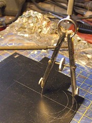 In the end I used good, old fashioned trial and error. After a few goes I got something that was about the same depth as the etched weight and carved the moon-shaped out of the plastic. These were then stuck in place using superglue.
The glue seemed to affect the plastic a little, probably because I used quite a lot to build up the depth. A little green filler and some smoothing down soon sorted this though.
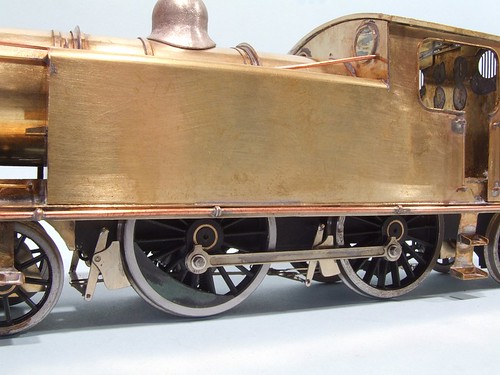
Once problem I did have was working out how far around the wheel the weights should be fitted. The photos appear to show the centre matching the crank-pin sometimes and other being slightly offset. I went with the former but if someone can prove me wrong then I might be up for modifying them.
6 comments:
I wonder if it would be worth photocopying a scale drawing and using the photocopy to make templates for this job?
Paul.
I think my technique is right - you want curves and the best way to cut those is with a compass. What I need is to know the correct sizes and the plan I have doesn't show wheel detail. It just shows though - you can never have too much information !
Surely the balance weights should be on the opposite side of the wheel to the crank pins, as they are to balance out the mass of the crank pins and coupling rod?
That's what I thought but the photos show different. I suspect the position of the drive on the axle affects things. Anyone who understand how chuff chuffs work care to comment ?
A steam engine has balance weights to counteract the cylinders, not the coupling rods.
The connecting rods are normally opposite, i.e. 180 degrees, from the cylinders to help counteract the cylinder 'hammer blow', as are the balance weights.
But don't quote me on this. This is the norm AFAIK - I'm no expert!
Yes, agree Matt. The balance weights counteract the dynamic forces of cylinders & reciprocating weights - so the only way for sure is use the photo! By the way Phil, do you find the green stuff ok for filling the back of the balance weight? I've just used some myself and hope it don't fall out! Previously used epoxy - and got myself in a right mess!
Post a Comment