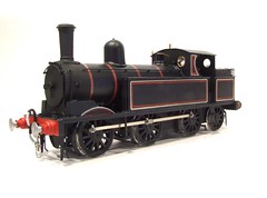
With a final push the coal tank is finished, and it looks good.
The locomotive kit is a good solid and reasonably simple one to assemble. Whilst it doesn't give you a Finney style level of detail that doesn't really matter. All the fundamentals seem right. If you want to ice this particular cake then you can do. I made a few improvements during the build but nothing major.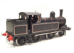 The real challenge was painting. Full lining is a first for me. I think the results have come up OK, but can see why you pay the money if you want one of the top painters to topcoat your model. The techniques aren't that difficult in theory but do require a confidence acquired only through practice.
In conclusion: Nice kit giving a very nice result.
Showing posts with label Coal tank. Show all posts
Showing posts with label Coal tank. Show all posts
Thursday, May 28, 2009
LNW Coal Tank

Wednesday, May 27, 2009
Buffer beam and couplings
Final push on the Coal Tank locomotive - fitting the buffers and couplings. There is something about this stage when the loco starts to look at it's best. Buffers are funny thing, some people get incredibly excited about them and will agonise for hours about the correct shanks for a particular model. Others (like me) are happy to have round things sticking out from the beam that have heads of about the right size. OK, so on a loco I can muster a bit of enthusiasm but on wagons ? Is it really that important ? Even if you have a tension lock in the immediate vicinity ?
Anyway, the buffers for this particular steam engine are the right ones according to the photos. Sadly, on the real thing they would be self-contained but on a model the springing requires a tiny shank sticking out through the back of the beam. Since this is sans hole, the retaining nut can only move in a very limited space - about 2mm I think. Mind you the springs in buffers rarely do much on a model and so a small movement ought to be sufficient and at least you don't get to see an unprototypical nut bouncing back and forth just under the footplate.
The couplings are quite a nice set of screws that can actually be tightened up should the operator desire and have nothing better to do. And have a screwdriver as the tightening is achieve with this... Still, they do look the part. Again the lack of space behind the front beam means this set aren't spring but Araldited in place. Curse the designer of the real engine who put as great void in front of the smoke box, leaving modellers with nowhere to hide stuff.
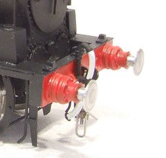
Anyway, the buffers for this particular steam engine are the right ones according to the photos. Sadly, on the real thing they would be self-contained but on a model the springing requires a tiny shank sticking out through the back of the beam. Since this is sans hole, the retaining nut can only move in a very limited space - about 2mm I think. Mind you the springs in buffers rarely do much on a model and so a small movement ought to be sufficient and at least you don't get to see an unprototypical nut bouncing back and forth just under the footplate.
The couplings are quite a nice set of screws that can actually be tightened up should the operator desire and have nothing better to do. And have a screwdriver as the tightening is achieve with this... Still, they do look the part. Again the lack of space behind the front beam means this set aren't spring but Araldited in place. Curse the designer of the real engine who put as great void in front of the smoke box, leaving modellers with nowhere to hide stuff.
Saturday, May 23, 2009
Boiler bands
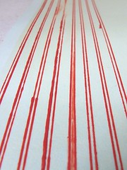 According to the book, the approved way of doing boiler bands on a model steam engine involved drawing the lines on some transfer paper and then using these home made decals on the model. Since I'm not in a position to disagree, and don't fancy my chances of running a bow pen round the boiler, under handrails and pipes, that's what I have done.
In my stock of stuff I had an unidentified A4 sheet of blank transfer paper. The bands were marked out as a series of dots 1mm apart. Than I took the bow pen that worked best for me and joined the dots with some nice red paint.
Working on the shiny paper made things difficult - on the finished body or a rubber cutting mat the paint is pulled from the pen. This doesn't happen on the paper as it's so slippery. The angle I held the pen at seemed to make a bit of a difference but the only plan that made sense involved making far, far to many bands and hoping I had enough good stuff to do the job.
Once dry I carefully cut the strips out and soaked then in water. The transfers seemed to take a long while to release from the backing paper and once off were very thin and difficult to handle. Once a band twisted on itself it was almost impossible to recover. Luckly I had almost twice as much bad as required even allowing for the duff early efforts that had to be thrown away.
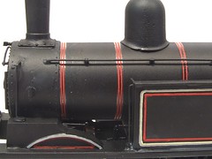 The end result is good. The transfer sheet gives enough thickness to represent the very thin strips of metal. Those lines look really good and once on the body could be poked around easily enough with a wet brush to make sure they were upright when viewed from the side.
One minor issue is in the kit instructions. Measurment are provided for setting the bands out but looking at the photos of finished model, these are wrong by a few mm. Follow these and the band comes out from under the dome when it should cross in front of it.
Friday, May 22, 2009
More lining
That grey lining look so good yesterday. Then I started with the red lines and realised that it wasn't as perfect as I though. In the end I spent an entire morning chasing around the coal tank locomotive body fiddling with paint.
First the red lines went on. Then I re-worked some of the grey ones which now appeared to be incorrect. Then added black between them where required. And repeated the whole process. Again. And again.
After a tea break I moved on the the last bit - on the inside edge of the grey line there is a cream one. Deep joy ! By this point I was getting my eye in and was finding some from my selection of bow pens easier to use than others. Those with a flat and curved tips didn't work quite as well for thin lines as those with two curved tips so I employed the later for the cream bits.
OK - so this isn't as good as one of the best pros would do it. I always say that I produce a "layout loco" rather than a glass case example, but I'm quite pleased with my lining. I'd certainly be happy to run it on any layout and I've seen a lot worse at shows. From normal viewing distane it looks good. You'd possibly get a slightly better result from transfers although I doubt it would be any less trouble to do - except in front of the cab where matching that curve would be impossible and on the splashers. Leaving these areas blank would be the best option I suspect..

First the red lines went on. Then I re-worked some of the grey ones which now appeared to be incorrect. Then added black between them where required. And repeated the whole process. Again. And again.
After a tea break I moved on the the last bit - on the inside edge of the grey line there is a cream one. Deep joy ! By this point I was getting my eye in and was finding some from my selection of bow pens easier to use than others. Those with a flat and curved tips didn't work quite as well for thin lines as those with two curved tips so I employed the later for the cream bits.
OK - so this isn't as good as one of the best pros would do it. I always say that I produce a "layout loco" rather than a glass case example, but I'm quite pleased with my lining. I'd certainly be happy to run it on any layout and I've seen a lot worse at shows. From normal viewing distane it looks good. You'd possibly get a slightly better result from transfers although I doubt it would be any less trouble to do - except in front of the cab where matching that curve would be impossible and on the splashers. Leaving these areas blank would be the best option I suspect..
Thursday, May 21, 2009
Grey lining
Here's a job I've been putting off for a few days. Lining. Obviously this was to allow the black base coat to dry properly rather than through any nervousness about the task...
I'd promised to try to paint this locomotive in full LNWR lined black. That means a grey line, red line and then inner cream line on the grey.
So I broke out the bow pen and a nice fresh tin of Humbrol 64 and had a go. It won't suprise you that I re-read the relevant sections of Rathbones' book on painting and lining first.
A piece of mircostrip was selected to act as a jig for marking the centre of the line. I used this against all the edges to ensure consistence. Just a little pencil dot showed up well against the sating black paint.
With some trepidation I thin loaded the pen and started work. With care I think the results aren't bad. Maintaining a constant rate of travel along the line with the pen seems to be the most important thing. The straight lines actually went on very fast.
The corners are brushed in with a tiny Humbrol paintbrush. Then the tidying up starts using the same paint, from the same can , that the engine is sprayed in. This is the bit that you don't get to hear about normally but according to Rathbone, is important - even the professionals don't get everything on exactly right first time !
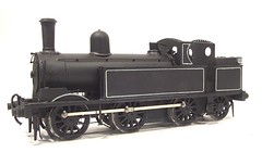
I'd promised to try to paint this locomotive in full LNWR lined black. That means a grey line, red line and then inner cream line on the grey.
So I broke out the bow pen and a nice fresh tin of Humbrol 64 and had a go. It won't suprise you that I re-read the relevant sections of Rathbones' book on painting and lining first.
A piece of mircostrip was selected to act as a jig for marking the centre of the line. I used this against all the edges to ensure consistence. Just a little pencil dot showed up well against the sating black paint.
With some trepidation I thin loaded the pen and started work. With care I think the results aren't bad. Maintaining a constant rate of travel along the line with the pen seems to be the most important thing. The straight lines actually went on very fast.
The corners are brushed in with a tiny Humbrol paintbrush. Then the tidying up starts using the same paint, from the same can , that the engine is sprayed in. This is the bit that you don't get to hear about normally but according to Rathbone, is important - even the professionals don't get everything on exactly right first time !
Friday, May 15, 2009
Locomotive driver and fireman
A steam engine needs a crew and the coal tank is no different. Finding footplate figures ought to be easy but I've often found the quality to be a bit iffy. In 4mm scale you are probably best off with the Monty's Models figures or the Alan Gibson ones if you can get them. Of course if you've lots of locomotives this could get a bit repetitive !
In O gauge I've plumped for Phoenix Miniatures sold by S&D Models, numbers OF23 & OF24 at £3 each. Both are excellent quality models which are a real pleasure to paint. Carving figures is probably the most difficult job you can undertake in railway modelling - if you want them to look right and not cartoonish anyway. I think Phoenix have a background in military modelling which shows. Those guys are pickier than railway fans in this respect. Some assembly of the pewter parts is required, the arm on the driver and arm and hand on the fireman which I carried out with superglue.
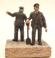 Painting followed my well worn methods - flesh from Humbrol and then dry brushed with Revell. waistcoats are dark blue or dark grey. Overalls are Precision Weathered Black. When this was nearly dry I covered it with talcum powder to take the shine off and then worked black powder paint into all the crevasses. Although the waistcoat colours became less obvious I think you can just about tell.
Finally the hair (head and facial) and eyes were done with a tiny brush. I like the moustache and bear, they were compulsory on railway worked in the early part of the 20th century as far as I can tell from photos so they give the crew the right look for a pre grouping locomotive.
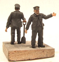
In O gauge I've plumped for Phoenix Miniatures sold by S&D Models, numbers OF23 & OF24 at £3 each. Both are excellent quality models which are a real pleasure to paint. Carving figures is probably the most difficult job you can undertake in railway modelling - if you want them to look right and not cartoonish anyway. I think Phoenix have a background in military modelling which shows. Those guys are pickier than railway fans in this respect. Some assembly of the pewter parts is required, the arm on the driver and arm and hand on the fireman which I carried out with superglue.
Painting followed my well worn methods - flesh from Humbrol and then dry brushed with Revell. waistcoats are dark blue or dark grey. Overalls are Precision Weathered Black. When this was nearly dry I covered it with talcum powder to take the shine off and then worked black powder paint into all the crevasses. Although the waistcoat colours became less obvious I think you can just about tell.Finally the hair (head and facial) and eyes were done with a tiny brush. I like the moustache and bear, they were compulsory on railway worked in the early part of the 20th century as far as I can tell from photos so they give the crew the right look for a pre grouping locomotive.
Thursday, May 14, 2009
Coal tank in primer
Thanks to some new photos showing the front end of this particular steam locomotive, I've been able to sort out the sanding gear mystery. My guess was correct, the operating mechanism from the cab only exists on the left hand side of the engine. From a lever on the side of the smokebox a rod goes to the right and pulls from that side.
Of course this throws up more questions - with the operating rod going through the smokebox, how did the holes to let it enter and exit affect steaming ? Why didn't it get covered in ash and muck seizing up ? Maybe it did as the linkage isn't obvious on later photos of this engine.
The sharp eyed will spot that there are two whistles. Apparently there is a normal one and one for the train crew to use, connected to the train with a bit of rope. No. I'm not modelling the rope.
Anyway, this put me into a position to prime the model. This has gone well despite my hairdryer having broken down so I had to rely on normal drying. Time for a new one I think.
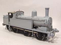
Of course this throws up more questions - with the operating rod going through the smokebox, how did the holes to let it enter and exit affect steaming ? Why didn't it get covered in ash and muck seizing up ? Maybe it did as the linkage isn't obvious on later photos of this engine.
The sharp eyed will spot that there are two whistles. Apparently there is a normal one and one for the train crew to use, connected to the train with a bit of rope. No. I'm not modelling the rope.
Anyway, this put me into a position to prime the model. This has gone well despite my hairdryer having broken down so I had to rely on normal drying. Time for a new one I think.
Tuesday, May 05, 2009
Sandbox mystery
The front of the coal tank is looking suitably complicated now but has thrown up a mystery. On the left hand side (looking at the front of the locomotive) there is a sandbox operating lever. The rod to work this appears to run through the handrail - a similar system is used on other steam engines so this isn't that unusual.
According to the kit instructions the linkage only appears on one side only though. Presumably there is a hidden mechanism in the smokebox or under the footplate to work both sides simultaneously. This would make sense as you'd want to do this and certainly wouldn't fancy working levers on both sides of the cab at the same time if at all possible. When sanding is required, the driver really needs to concentrate on the regulator rather than flailing around like an octopus.
Of course photos would clear this up but there are very few of this engine in original condition and those that there are are inconclusive or even contradictory. That's one of the problems with modelling pre-grouping and one of the benefits - there is less chance of being proved wrong !
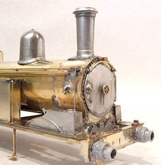
According to the kit instructions the linkage only appears on one side only though. Presumably there is a hidden mechanism in the smokebox or under the footplate to work both sides simultaneously. This would make sense as you'd want to do this and certainly wouldn't fancy working levers on both sides of the cab at the same time if at all possible. When sanding is required, the driver really needs to concentrate on the regulator rather than flailing around like an octopus.
Of course photos would clear this up but there are very few of this engine in original condition and those that there are are inconclusive or even contradictory. That's one of the problems with modelling pre-grouping and one of the benefits - there is less chance of being proved wrong !
Monday, May 04, 2009
Finished chassis
No great problems finishing off the chassis for the coal tank locomotive. With the wheels out, a coat of primer and then a brush painted covering of Humbrol matt black. This is an excellent brushing paint and application by hand gives a slightly thicker, and therefore more robust, coat than spraying. Besides, it's easier to get paint into all the nooks and crannies this way.
With the paint dry AND hard the wheels, motor and gears went back in. With all well the pickups were fitted and tested. I love watching a chassis I've built run up and down the test track and probably do this a bit more than absolutely necessary. Of course it is important to get things run in properly of course...
The brakes are soldered to the support wires next. Using Cars Red flux is important as it's non-corrosive. I can't stick the chassis under a tap at this point to clean it up, hence the specialist but less effective flux. The same stuff is used for the pull rods which on this steam loco, go on the outside of the wheels. The curved hangers and outside rods are part of making this early prototype as elegant as it is.
After another quick(ish) test the chassis is now on the shelf waiting for me to finished the body. And yes, I have checked that this still fits,
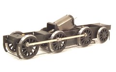
With the paint dry AND hard the wheels, motor and gears went back in. With all well the pickups were fitted and tested. I love watching a chassis I've built run up and down the test track and probably do this a bit more than absolutely necessary. Of course it is important to get things run in properly of course...
The brakes are soldered to the support wires next. Using Cars Red flux is important as it's non-corrosive. I can't stick the chassis under a tap at this point to clean it up, hence the specialist but less effective flux. The same stuff is used for the pull rods which on this steam loco, go on the outside of the wheels. The curved hangers and outside rods are part of making this early prototype as elegant as it is.
After another quick(ish) test the chassis is now on the shelf waiting for me to finished the body. And yes, I have checked that this still fits,
Sunday, May 03, 2009
Brake hanger jig
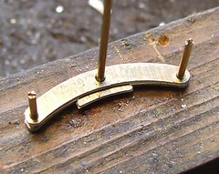 Normally I can't be bothered to make jigs. Obviously for many people if you are carrying out a repetitive job it makes complete sense to construct a tool to ensure consistency in construction. Often the time spent making the jig is more than saved in increased production speed to say nothing of improved accuracy.
Me - I'm normally too lazy and will struggle on rather than devise something to help.
Not this time though - 6 brake hangers for wooden brake shoes were required and even I spotted that trying to hold all the parts in place and wield a hot soldering iron was a recipe for frustration. Well, that and I realised that the jig needed to be no more than three holes drilled in a bit of wood and couple of lengths of wire.
T o use the jig, the first hanger was threaded over the wires. Then the brake shoe and second hanger were put on the middle one and then on top of the first. The shoe was soldered in place with loads of flux and a reasonable slug of solder. Finally the centre wire was chopped back to become the pivot the shoe hangs on. Simple and effective, a bit like me really !
Saturday, May 02, 2009
Pickups
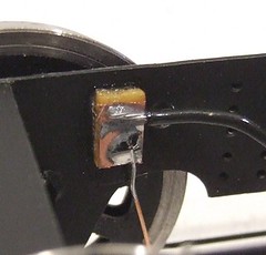
I've always had a problem with fitting model locomotive pickups. Normally these are attached to a PCB strip fitted across the chassis. Phosphor bronze wire is my favoured medium - it's nice an flexible so seems to stay in contact with the back of the wheel better than any other metal.
Getting the tension right has always been a fiddle. I tend to settle for soldering the wire in place and then tweaking it around with small pliers to get it in position. This might work but doesn't seem like proper engineering to me.
On the coal tank I've been able to do things a little better than I have with previous attempts. There is enough space in the chassis to give each pickup its own bit of PCB. That makes things easier as soldering a wire in place doesn't dislodge other wires. It also keeps the bronze wires out of danger under the chassis. This might sound daft until you have heard someone describe the results of an O gauge locomotive running over a slug on his garden railway !
The PCB scraps, cut from OO sleeper strip[, were glued in place with superglue. A wire joined them together and on to the motor. Finally the pickup wire was pre-bent and soldered on. There was still some tweaking required but it's not as bad as previous efforts.
Incidentally, the chassis is supplied with holes in place for plunger pickups. I have tried these and when they work they are great. The downside is that any maintenance requires the removal of the locomotive driving wheels as access into the plunger is from the front. So a sticky spring, not an uncommon complaint, requires major work to fix. I suspect you'd look at this and decide to bodge it with a bit of wire making a scraper !
Getting the tension right has always been a fiddle. I tend to settle for soldering the wire in place and then tweaking it around with small pliers to get it in position. This might work but doesn't seem like proper engineering to me.
On the coal tank I've been able to do things a little better than I have with previous attempts. There is enough space in the chassis to give each pickup its own bit of PCB. That makes things easier as soldering a wire in place doesn't dislodge other wires. It also keeps the bronze wires out of danger under the chassis. This might sound daft until you have heard someone describe the results of an O gauge locomotive running over a slug on his garden railway !
The PCB scraps, cut from OO sleeper strip[, were glued in place with superglue. A wire joined them together and on to the motor. Finally the pickup wire was pre-bent and soldered on. There was still some tweaking required but it's not as bad as previous efforts.
Incidentally, the chassis is supplied with holes in place for plunger pickups. I have tried these and when they work they are great. The downside is that any maintenance requires the removal of the locomotive driving wheels as access into the plunger is from the front. So a sticky spring, not an uncommon complaint, requires major work to fix. I suspect you'd look at this and decide to bodge it with a bit of wire making a scraper !
Friday, May 01, 2009
Polished dome
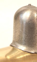
The whitemetal casting for the dome isn't the best I've ever seen but it can be made good. Luckily a spigot is cast in the bottom and this can be fitted in a chuck which in turn fits into an electric screwdriver. Don't use a power drill for this if you are trying the same thing - the screwdriver, being slower, is much more finger friendly.
Rotating the dome I cleaned the surface with some flexible grit stuff. Then the metal is given a good polish using some Brasso wadding. This always brings whitemetal to a nice shine. I think it looks like pewter rather than a lead based alloy. Whatever, this is a job worth doing and hopefully will result in a top quality finish once painted.
Rotating the dome I cleaned the surface with some flexible grit stuff. Then the metal is given a good polish using some Brasso wadding. This always brings whitemetal to a nice shine. I think it looks like pewter rather than a lead based alloy. Whatever, this is a job worth doing and hopefully will result in a top quality finish once painted.
Wednesday, April 29, 2009
Socket Lamp Irons
These are new to me - LNW socket lamp irons. I'm not sure why this railway company decided to be different from everyone else in the way they attached their lamps to locomotives, but as a modeller I wish that everyone else had done the same thing.
The sockets are supplied as very neat lost wax castings. All I had to do was snip them off from the fret and clean the backs with a file. Then, after tinning with conventional solder, I used the RSU to fit them to the loco. That's a nice quick process and a whole lot less painful than bending bits of etch to make a conventional lamp iron. The results are a whole lot less vulnerable to handling too !

The sockets are supplied as very neat lost wax castings. All I had to do was snip them off from the fret and clean the backs with a file. Then, after tinning with conventional solder, I used the RSU to fit them to the loco. That's a nice quick process and a whole lot less painful than bending bits of etch to make a conventional lamp iron. The results are a whole lot less vulnerable to handling too !
Tuesday, April 28, 2009
Coal Tank front steps
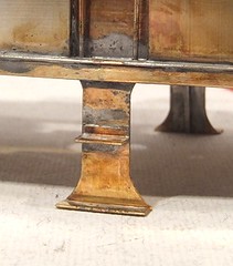
Yet another moment when I wonder about the sanity of the designer of this steam engine. The front steps dangle from an impossibly slender strip. Even in 7mm scale this is less than 2mm wide.
The parts are nicely etched of course. I decided against popping a rivet in the upright as I doubted this can be done without mangling the metal, or at least I don't believe I could do it. What I can do is beef this part up so the model can be handled without fear of damage. In the rear of each step the widest bit of wire I could hide has been soldered on. This worked better than expected and has really strengthened the part.
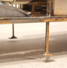
 At the back the steps are much more conventional. Despite this I was so pleased with the hidden wire I did it again here. It's not unknown for these to deform although as there isn't a slot to locate the centre step, this traditional weak spot isn't present.
By the time I got to attaching these parts, the mass of metal in the model had grown so large that the best way of fixing parts is with a gas torch rather than traditional iron. In with the heat, melt the solder, fix the part and then back out again letting things cool down. No burnt fingers this way !
The parts are nicely etched of course. I decided against popping a rivet in the upright as I doubted this can be done without mangling the metal, or at least I don't believe I could do it. What I can do is beef this part up so the model can be handled without fear of damage. In the rear of each step the widest bit of wire I could hide has been soldered on. This worked better than expected and has really strengthened the part.
At the back the steps are much more conventional. Despite this I was so pleased with the hidden wire I did it again here. It's not unknown for these to deform although as there isn't a slot to locate the centre step, this traditional weak spot isn't present.By the time I got to attaching these parts, the mass of metal in the model had grown so large that the best way of fixing parts is with a gas torch rather than traditional iron. In with the heat, melt the solder, fix the part and then back out again letting things cool down. No burnt fingers this way !
Monday, April 27, 2009
Sorting out the underpinnings

A couple of weeks ago I expressed some reservations on the design of the Coal Tank locomotive's back end. The bogie seemed to offer far too much movement for the axle which flopped back and forth rather more than it should have done, not to the detriment of the track holding though.
Apparently this was all down to a packing error and I should have received an extra set of axle bearings. With these now fitted the wheels stay where they are supposed to. The bogie, while pretending to be a radial truck, will still move from side to side and up and down so I still expect the wheels to stay in contact with the track. The keen eyed will notice that I fitted the "top hats" pointing out rather than it - this should allow me to limit the side play by filing them down as required. I want to stop the flanges touching the frames if possible. We don't want to wear the paint or cause any possible short circuits. At the front some fake frames are attached to the body. This is because there is a hole in front of the smokebox which is wider than the working frames. These stop behind the cylinder fronts, the curvy bit sticking down in the photo. Perhaps if I was building in S7 this wouldn't be a problem but then the kits not designed for that (Note: The Coal Tank kit now comes with a different chassis than the one I'm building so things may all be different). I wasn't happy with the shape of these so re-made them from some scrap etch. My version also fits rather better to my mind too. It looks just as good too. At least the body now sits down properly.
And yes there are guard irons to go on but if I do them now I'll spend the next few days sticking them in my fingers or beding them every time I put the body down on the bench.
Thursday, April 23, 2009
Locomotive beading
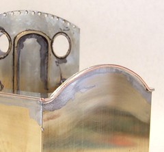 Time to pretty up this steam engine with some beading. According to the instructions in the kit this is carried out with bits of brass etch including bits of scrap from the leftover metals. Nuts to that, I prefer to use a trick passed on to me by John Sutton, editor of the 3mm Scale Society magazine.
Simply take some normal fuse wire, 30 Amp in this case or the fatest one of the card, clamp one end in a vice and pull the other. This straightens the wire. The solder it to the top edges of the tanks and other parts to be decorated. Fuse wire is tinned copper so it solders easily with a bit of flux. To finish off, polish with a fibre stick and a lovely job is the result.
I go a bit further and bead the whole length of the tank tops in one go, bridging the cab door in the process. This ensures a nice straight line and I can open the door up later with some wire cutters.
Wednesday, April 22, 2009
Don't be blue.
I've decided to start painting the loco and in a revolutionary move will be colouring it in with marker pen. Far easier than messing around with paint I think.
Only kidding. The marker pen currently spoiling the lovely brassiness of the coal tank locomotive boiler is my version of engineers blue. Blue is a liquid painted on to metal before marking out so that the scribed lines show nice and clearly - on untouched metal you have to get the light right by looking at odd angles to see your line. Either that or scribe it so deeply that you can still see it after painting, neither of which can be called A Good Thing.
Trouble is it's horrible stuff. It stains your fingers and seems a very messy way of working in an age of computers and pop tarts. I prefer to use a permanent marker pen which is easier to apply and works just as well. Don't worry about the cleaning off either - Shiny Sinks removes it when cleaning up after a soldering session.
The marking out is for handrail holes. The boiler doesn't come pre drilled so I have to do this the hard way. First a line is established parallel with the footplate using an oddleg or Jenny caliper. The dividers are set to provide the spacing and scribe the vertical lines. Finally the centre is each cross has a scriber pushed into it to give a dimple that guides the drill bit.
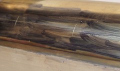
Only kidding. The marker pen currently spoiling the lovely brassiness of the coal tank locomotive boiler is my version of engineers blue. Blue is a liquid painted on to metal before marking out so that the scribed lines show nice and clearly - on untouched metal you have to get the light right by looking at odd angles to see your line. Either that or scribe it so deeply that you can still see it after painting, neither of which can be called A Good Thing.
Trouble is it's horrible stuff. It stains your fingers and seems a very messy way of working in an age of computers and pop tarts. I prefer to use a permanent marker pen which is easier to apply and works just as well. Don't worry about the cleaning off either - Shiny Sinks removes it when cleaning up after a soldering session.
The marking out is for handrail holes. The boiler doesn't come pre drilled so I have to do this the hard way. First a line is established parallel with the footplate using an oddleg or Jenny caliper. The dividers are set to provide the spacing and scribe the vertical lines. Finally the centre is each cross has a scriber pushed into it to give a dimple that guides the drill bit.
Tuesday, April 21, 2009
Splasher
At last, some whitemetal bits. Ok so the bits are major component rather than detailing parts but it's a nice change from all that brass. The splashers are nice clean castings that just need a touch of trueing up at the front. I suppose the designer could have made them up as etched parts but suspect that the sheets were already full so castings were the way to go.
The spring poking out from the back is a clever part - what you see is what you get. The rest of the spring simply doesn't exist. Likewise the reversing lever stops just out of sight behind the tank. Some might feel cheated by this but for a model intended for use is it clever to spend time making parts that are never seen ?
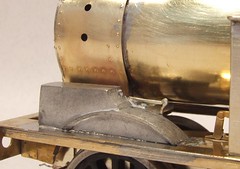
The spring poking out from the back is a clever part - what you see is what you get. The rest of the spring simply doesn't exist. Likewise the reversing lever stops just out of sight behind the tank. Some might feel cheated by this but for a model intended for use is it clever to spend time making parts that are never seen ?
Saturday, April 18, 2009
Chip fork tools
Having bolted the boiler into the coal tank locomotive I proceeded to tack solder the new lump of brass to the side tanks. Since it was late I planned to stop work once the tacks had cooled and take another look in the morning. Sometimes what looks good in the evening can appear wonky the next day. I like to think this is due to the metal cooling overnight and not my own stupidity, but whatever the cause, I've been caught out like this before and learned my lesson.
However as soon as I looked at the model from the front it was obvious that the side tanks were both leaning in at the top. Handy for aerodynamics if this were a VTOL steam engine but a bit rubbish for the model I'm building. The problem stems from the tack solder joins pulling the tanks and boiler together. Of course there should be a gap between them. I couldn't leave it like this and had to fix the problem imediatly.
Heating up the solder blobs took more effort that expected and it quickly became obvious that even with a gas torch I wasn't going to get both sides separate at the same time. Plan B therefore involved heating the join and stuffing a spacer in to force the gap.
Now I'm not posh. When I occasionally eat chips after the odd beer I use my fingers. It's not that I'm too drunk to accuratly stab a chip with a fork, it's just that chips in paper are perfectly natural and shouldn't involve cutlery, even of the temporary wooden sort. Despite this my local takeaway insists on proving me with a chip fork. Sensible people would throw these away but I stick them in the same drawer that contains half a forest worth of wooden coffee stirrers. I find all sorts of wooden utensils useful for holding hot metal while soldering so it's not such a daft idea.
Anyway, a pair of chip forks slightly sharpened worked a treat for putting the boiler-tank space in. The forked ends span the tabs in the inside tank sides that support the boiler. There's probably a proper engineers way to do this but this is cheaper and you get chips too !
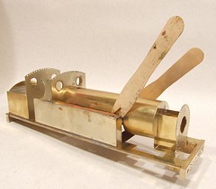
However as soon as I looked at the model from the front it was obvious that the side tanks were both leaning in at the top. Handy for aerodynamics if this were a VTOL steam engine but a bit rubbish for the model I'm building. The problem stems from the tack solder joins pulling the tanks and boiler together. Of course there should be a gap between them. I couldn't leave it like this and had to fix the problem imediatly.
Heating up the solder blobs took more effort that expected and it quickly became obvious that even with a gas torch I wasn't going to get both sides separate at the same time. Plan B therefore involved heating the join and stuffing a spacer in to force the gap.
Now I'm not posh. When I occasionally eat chips after the odd beer I use my fingers. It's not that I'm too drunk to accuratly stab a chip with a fork, it's just that chips in paper are perfectly natural and shouldn't involve cutlery, even of the temporary wooden sort. Despite this my local takeaway insists on proving me with a chip fork. Sensible people would throw these away but I stick them in the same drawer that contains half a forest worth of wooden coffee stirrers. I find all sorts of wooden utensils useful for holding hot metal while soldering so it's not such a daft idea.
Anyway, a pair of chip forks slightly sharpened worked a treat for putting the boiler-tank space in. The forked ends span the tabs in the inside tank sides that support the boiler. There's probably a proper engineers way to do this but this is cheaper and you get chips too !
Friday, April 17, 2009
Smokebox
Look at those lovely rivets !
The photo doesn't show clearly the beautiful curves around the perimeter of the smokebox or ends of the cylinders but be assured, they are there. It's one of the design details that make a pre-grouping steam locomotive - an air of elegance that somehow went missing in later years.
As usual the lumps are courtesy of the GW Models press and followed the half-etch dimples in the back of the part. One impressed the front and back of the box were joined with stretchers. Interestingly these are brass as opposed to the nickel faces. I assume this is to make best use of the metal in the etching process. Locating bits is a touch harder when they are spread across two different sheets, but not enough to worry about.
The boiler arrived pre-rolled. I just had to solder the seam at the bottom and then fit the formers at front and back. These incorporate holes to allow the boiler to be bolted to the smokebox and cab front. Normally I ignore these and go straight in with the soldering iron but this time I've used them so I can ensure nice alignment of this major part.
Mind you, trying to do up the front bolt was "entertaining" as none of my screwdrivers fitted properly into the space under the loco, something always seemed to be in the way. Hindsight tells me that a nut spinner would have been better to start things off than a pair of pliers but at the time it didn't occur to me.

The photo doesn't show clearly the beautiful curves around the perimeter of the smokebox or ends of the cylinders but be assured, they are there. It's one of the design details that make a pre-grouping steam locomotive - an air of elegance that somehow went missing in later years.
As usual the lumps are courtesy of the GW Models press and followed the half-etch dimples in the back of the part. One impressed the front and back of the box were joined with stretchers. Interestingly these are brass as opposed to the nickel faces. I assume this is to make best use of the metal in the etching process. Locating bits is a touch harder when they are spread across two different sheets, but not enough to worry about.
The boiler arrived pre-rolled. I just had to solder the seam at the bottom and then fit the formers at front and back. These incorporate holes to allow the boiler to be bolted to the smokebox and cab front. Normally I ignore these and go straight in with the soldering iron but this time I've used them so I can ensure nice alignment of this major part.
Mind you, trying to do up the front bolt was "entertaining" as none of my screwdrivers fitted properly into the space under the loco, something always seemed to be in the way. Hindsight tells me that a nut spinner would have been better to start things off than a pair of pliers but at the time it didn't occur to me.
Subscribe to:
Posts (Atom)