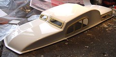
While I wait for the next trip to the lake for testing I might as well get on with the rest of the model boat kit. Next task on the list is to fit the windows.
These come as a series of resin castings. They suffer a little from flash but this is very easily removed with a sharp knife. The sort of job that I’d rather do myself than pay the manufacturer to do for me. This is after all a kit that requires modelling skills, not a plastic kit that can be stuck together by a three-year-old. Not that it is difficult, just that you need to engage your brain before grasping the sharp end of the knife. Always grab the blunt bit kids ! (That was a public service announcement for the terminally dim).
Anyway, the window frames are fitted on the outside of the superstructure. First though you have to cut away the plastic so the windows are open. I marked the holes to cut by holding the frame in place and then running a fine CD marker pen round the inside. These pens came from a pound shop in a CD marking kit – 3 colours, two of each, What a bargain. A special pen is needed because pencils and normal pens won’t mark the very shiny surface of the vac-formed plastic.
The holes were then cut oversize to allow for glazing to be glued in to the back of the frames and flush with the plastic superstructure. Superglue attached the frames and coated my finger tips but it seems to have held.
Only ones I had the funny shaped side windows in place did I notice the nearly imperceptible mark on the surface where I am supposed to put them. I’m not worried, they look OK to me.
Wednesday, September 20, 2006

Monday, September 18, 2006
Drive shaft
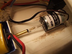
Every time I take my latest boat down to the lake there is a problem with the drive. The model travels about 20 feet and then the neopropaline tube that accts as the coupling between motor and drive shaft slips off. This is annoying and more importantly, embarrassing when it happens in front of other people.
I think that the drive shaft is too thin for the tube. If it were fatter presumably the tube would be stretched and grip properly.
My solution (I hope) was to take a bit of brass tube and ream the inside so the shaft would go inside. Needless to say this wasn’t easy (the simple looking jobs never are) as holding a tube is difficult. I tired pin vices and clamps with varying degrees of success. I don’t own a 1.6mm diameter drill bit either, hence the reaming.
After nearly an hour I had a short tube that would slip over the drive shaft and with the aid of some superglue, stay put.
The neoprop tube seems to fit nice and snugly and certainly looks like it will stay put. I suppose I’ll have to take it out on the water to be sure.
The curse of the camera strikes again by the way. The shaft and motor are lined up a whole lot better than they appear in the picture, although I admit they aren’t perfect.
I think that the drive shaft is too thin for the tube. If it were fatter presumably the tube would be stretched and grip properly.
My solution (I hope) was to take a bit of brass tube and ream the inside so the shaft would go inside. Needless to say this wasn’t easy (the simple looking jobs never are) as holding a tube is difficult. I tired pin vices and clamps with varying degrees of success. I don’t own a 1.6mm diameter drill bit either, hence the reaming.
After nearly an hour I had a short tube that would slip over the drive shaft and with the aid of some superglue, stay put.
The neoprop tube seems to fit nice and snugly and certainly looks like it will stay put. I suppose I’ll have to take it out on the water to be sure.
The curse of the camera strikes again by the way. The shaft and motor are lined up a whole lot better than they appear in the picture, although I admit they aren’t perfect.
Saturday, September 16, 2006
Tomkat's ninth life
Hooray – The Tomkat is working again !
Since I still feel rubbish for not making Shipley, I thought I ‘d do one of those jobs I didn’t want to do in way of atonement. Stupid really but I digress. The job was removing all the useful bits from the boat before it made a voyage into the bin.
Pulling it apart I found a loose bolt stuck to the motor but this didn’t look like the problem. Removing it and connecting the terminals to a battery still gave short – or that spark and crack that indicates there is one. I twisted the shaft by hand and tried again. This time there was life.
Sooooo, I reassembled everything and still had no luck. Then I tested to see if there was life from the speed control. According to the meter I connected up the power coming out was reversing even though the voltage didn’t. Good news so far. Still nothing when the motor was connected.
Next I removed the speed control from my new boat and wired it up with the aid of crocodile clips and bits of wire (very useful things croc clips). Everything seemed fine.
The Tomkat control was wired into the new boat (are you following this) and worked. Intermittently. A little experimentation and waggling of wires indicated a loose connection in the plug. At last – a problem I could fix !
So the Tomakt now works with the motor to speed control plug & socket replaced with a chocolate block. A trip to the lake had the boat whizzing around as much as two nearly flat batteries allowed. Enough to show that we might be back in action though.
Fingers crossed, the last round of the competition is next weekend and it would be nice to take part in one leg.

Since I still feel rubbish for not making Shipley, I thought I ‘d do one of those jobs I didn’t want to do in way of atonement. Stupid really but I digress. The job was removing all the useful bits from the boat before it made a voyage into the bin.
Pulling it apart I found a loose bolt stuck to the motor but this didn’t look like the problem. Removing it and connecting the terminals to a battery still gave short – or that spark and crack that indicates there is one. I twisted the shaft by hand and tried again. This time there was life.
Sooooo, I reassembled everything and still had no luck. Then I tested to see if there was life from the speed control. According to the meter I connected up the power coming out was reversing even though the voltage didn’t. Good news so far. Still nothing when the motor was connected.
Next I removed the speed control from my new boat and wired it up with the aid of crocodile clips and bits of wire (very useful things croc clips). Everything seemed fine.
The Tomkat control was wired into the new boat (are you following this) and worked. Intermittently. A little experimentation and waggling of wires indicated a loose connection in the plug. At last – a problem I could fix !
So the Tomakt now works with the motor to speed control plug & socket replaced with a chocolate block. A trip to the lake had the boat whizzing around as much as two nearly flat batteries allowed. Enough to show that we might be back in action though.
Fingers crossed, the last round of the competition is next weekend and it would be nice to take part in one leg.
Friday, September 15, 2006
Shipley no show
After all that effort, thanks to transport problems (which aren't even old VW related) Flockburgh won't now be appaering at Shipley because we can't get there.
I feel terrible about this as this leaves the manager with a hole in his show and public who see one less layout than they have paid to see.
I feel terrible about this as this leaves the manager with a hole in his show and public who see one less layout than they have paid to see.
Wednesday, September 13, 2006
Exhibition Box
Flockburgh is due to attend the Shipley show this weekend. Previous postings have covered setting the layout up to make sure everything works. Now it’s time to get the thing packed up and ready for the journey.
Actually, that’s not true. Traditionally I manage to leave most of the packing until the night before and then wish I’d done it earlier. Not this time – because we had the photos taken at the club, which meant moving the model, packing was carried out nearly a week ago.
The last jobs to be done are usually assembling the toolbox and exhibition box.
Toolbox is easy. Open box, chuck the tools I think I might need in and close it again. Re-open, put the forgotten tools in and then close. Repeat three or four time. Ideally the box sits on the bench for a couple of days as I gradually fill it with items that make sense but hopefully will stay inside for the whole show. I don’t like fixing stuff if I can help it, but should the need arise I don’t want the tool two hundred miles away !
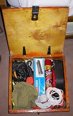
The exhibition box is special. For a start it is a wooden “Hatching Eggs” box I acquired from MAFF when I worked there twelve years ago. Into this I our all the leads, bolts, transformers, controllers, spare tools too big for the toolbox, cloths for cleaning, spare light bulbs and other stuff I think I will need for setting up. It’s a tight squeeze in there but I’ve packed it often enough to know roughly how to fit everything inside.
After the show the packing re-commences. One trick is to leave out the roll up extension lead. This frees enough space for a tired exhibitor to get the contents back in without making too much effort. This lead only goes in on the outward journey so I don’t forget it. I’ve not left it out of the jumble in the car on the way home – yet.
This is the end of exhibitions most model railway modellers never see. It’s not all about playing trains, you have to be a one (OK, two) man band and take everything with you. No one wants to go hunting for a four-way block in a strange town when the shop opens only an hour before the show. So next time you give a layout at a show less than thirty seconds of your time, think of the poor, bleary eyed owner who is wondering quite why he does this…
Actually, that’s not true. Traditionally I manage to leave most of the packing until the night before and then wish I’d done it earlier. Not this time – because we had the photos taken at the club, which meant moving the model, packing was carried out nearly a week ago.
The last jobs to be done are usually assembling the toolbox and exhibition box.
Toolbox is easy. Open box, chuck the tools I think I might need in and close it again. Re-open, put the forgotten tools in and then close. Repeat three or four time. Ideally the box sits on the bench for a couple of days as I gradually fill it with items that make sense but hopefully will stay inside for the whole show. I don’t like fixing stuff if I can help it, but should the need arise I don’t want the tool two hundred miles away !
The exhibition box is special. For a start it is a wooden “Hatching Eggs” box I acquired from MAFF when I worked there twelve years ago. Into this I our all the leads, bolts, transformers, controllers, spare tools too big for the toolbox, cloths for cleaning, spare light bulbs and other stuff I think I will need for setting up. It’s a tight squeeze in there but I’ve packed it often enough to know roughly how to fit everything inside.
After the show the packing re-commences. One trick is to leave out the roll up extension lead. This frees enough space for a tired exhibitor to get the contents back in without making too much effort. This lead only goes in on the outward journey so I don’t forget it. I’ve not left it out of the jumble in the car on the way home – yet.
This is the end of exhibitions most model railway modellers never see. It’s not all about playing trains, you have to be a one (OK, two) man band and take everything with you. No one wants to go hunting for a four-way block in a strange town when the shop opens only an hour before the show. So next time you give a layout at a show less than thirty seconds of your time, think of the poor, bleary eyed owner who is wondering quite why he does this…
Tuesday, September 12, 2006
Troubled waters part 2
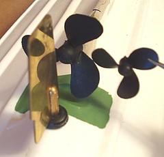
OK, so I have replaced the propeller on my model boat with a much bigger one. It looks like it should shift much more water and therefore to my simple mind the boat should go faster.
You should just be able to see that I had to fit a channel in the hull as the blades needed a bit of clearance. Filing away with a round file gave me the space and the thickness of the plastic hull meant that I had plenty of “meat” to stick some plasticard to. Once the joint hardened a bit of carefully sanding and trimming with a sharp knife made for a neat job. The paint is just to show how effective I’ve been as it’s difficult to see in the raw plasticard.
Back on the water, the boat accelerates a bit more effectively and then stops. The motor still turns but there is no propulsion. Thanks to the other model sailors making waves the boat eventually made its way to the most awkward and muddy part of the back for recovery.
The problem is with the coupling between motor and drive shaft. A bit of neopropaline tube has been used which is fine for small propellers but doesn’t look like it has enough grip on the drive shaft with this much torque.
You should just be able to see that I had to fit a channel in the hull as the blades needed a bit of clearance. Filing away with a round file gave me the space and the thickness of the plastic hull meant that I had plenty of “meat” to stick some plasticard to. Once the joint hardened a bit of carefully sanding and trimming with a sharp knife made for a neat job. The paint is just to show how effective I’ve been as it’s difficult to see in the raw plasticard.
Back on the water, the boat accelerates a bit more effectively and then stops. The motor still turns but there is no propulsion. Thanks to the other model sailors making waves the boat eventually made its way to the most awkward and muddy part of the back for recovery.
The problem is with the coupling between motor and drive shaft. A bit of neopropaline tube has been used which is fine for small propellers but doesn’t look like it has enough grip on the drive shaft with this much torque.
Monday, September 11, 2006
Merchant Navy - Finished
The title says it all. You are looking at a finished model railway locomotive.
I’m very pleased with it.
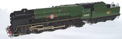
I’m very pleased with it.
Sunday, September 10, 2006
Lights, Camera, Action !
Ray Lightfoot from British Railway Modelling spent a couple of hours taking shots from all angles. He admitted afterwards that this had taken longer than he thought as although it looks like a simple little layout when you first see it, look closer and there is a lot more to see than you expect.
All the pictures were taken digitally and then checked on a laptop when the card in the camera was full. For techies the main camera was a 9mp Fuji 9500 and the smaller one a Nikon Coolpix with 5mp. Apparently both will produce an A4 shot suitable for publication but the Fuji with its higher resolution is also suitable for cover pictures. No idea what the difference is but then he is the expert.
My role was to make put locomotives and trains in the appropriate places and suggest some of the shots. And to hold the “sky” (a £4 roll of sky blue cloth from the market) when required. Although the pictures can be digitally manipulated to remove bookshelves and other background, we used the railway club as it gave more working space, a plain blue background makes the job quicker. We also diffused the strong sunlight with the sheet to avid annoying dark shadows.
All this electronic stuff contrasts with the first time I had a layout shot for a mag. That involved a medium format camera and resulted in 10 or 12 photos. All first class and beautifully framed but the photographer must always have been worrying what would happen if none of them came out !
I have no idea when the pictures will appear. Proofs will be supplied in due course and then there is the little matter of some words to accompany them.

All the pictures were taken digitally and then checked on a laptop when the card in the camera was full. For techies the main camera was a 9mp Fuji 9500 and the smaller one a Nikon Coolpix with 5mp. Apparently both will produce an A4 shot suitable for publication but the Fuji with its higher resolution is also suitable for cover pictures. No idea what the difference is but then he is the expert.
My role was to make put locomotives and trains in the appropriate places and suggest some of the shots. And to hold the “sky” (a £4 roll of sky blue cloth from the market) when required. Although the pictures can be digitally manipulated to remove bookshelves and other background, we used the railway club as it gave more working space, a plain blue background makes the job quicker. We also diffused the strong sunlight with the sheet to avid annoying dark shadows.
All this electronic stuff contrasts with the first time I had a layout shot for a mag. That involved a medium format camera and resulted in 10 or 12 photos. All first class and beautifully framed but the photographer must always have been worrying what would happen if none of them came out !
I have no idea when the pictures will appear. Proofs will be supplied in due course and then there is the little matter of some words to accompany them.
Friday, September 08, 2006
Axle Box
Just when I thought I might be finished I remember that the Merchant Navy is missing an axlebox.
Early in the project I had noticed that the rear pony wheels were more exposed than they should be. At the time I hoped to get a replacement casting from the kit manufacturer so the missing part would be easy to replace. No sign of it though so I had to improvise.
Luckily there was only one missing box and I could use that to base my replacement on. If I had the stuff available a mould would have been taken and a new part cast in polyester resin. As it wasn’t a crude plasticard facsimile was knocked up instead.
As the model is destined to be a layout locomotive and not a glass case example my version will look fine. It’s not far off the quality of the real casting and will certainly past muster as the model rushes past at the head of a train. Even standing still the eye won’t see it – just the whole model. If the wheel was still naked then you’d spot it though !
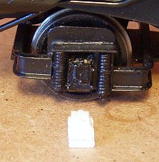
Early in the project I had noticed that the rear pony wheels were more exposed than they should be. At the time I hoped to get a replacement casting from the kit manufacturer so the missing part would be easy to replace. No sign of it though so I had to improvise.
Luckily there was only one missing box and I could use that to base my replacement on. If I had the stuff available a mould would have been taken and a new part cast in polyester resin. As it wasn’t a crude plasticard facsimile was knocked up instead.
As the model is destined to be a layout locomotive and not a glass case example my version will look fine. It’s not far off the quality of the real casting and will certainly past muster as the model rushes past at the head of a train. Even standing still the eye won’t see it – just the whole model. If the wheel was still naked then you’d spot it though !
Wednesday, September 06, 2006
Tail lights
Last job – paint the lights on the back of the Merchant Navy. Despite the model being in 7mm scale, they don’t work (Steam loco people are less keen on this sort of thing than their diesel comrades) being whitemetal castings. A touch of colour on the lens makes them look more like they could work.
Ideally a dark but imperceptibly red paint is required. I find gunmetal looks OK once it has a bit of gloss varnish on it as well. Mind you the camera makes them look matt which is most annoying. Never mind, at least this is another project finished and ready for the rails.
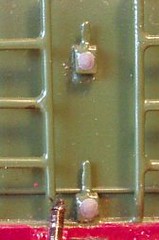
Ideally a dark but imperceptibly red paint is required. I find gunmetal looks OK once it has a bit of gloss varnish on it as well. Mind you the camera makes them look matt which is most annoying. Never mind, at least this is another project finished and ready for the rails.
Tuesday, September 05, 2006
Troubled waters
All model boats have to sail sometime and my new launch is no exception. I decided that I’d get the bare minimum of work done before she hit the water. Hence the propeller and rudder were installed along with the radio control bits – then we headed to the lake.
Actually I did check that she wasn’t going to sink using the bath but this was the proper maiden voyage.
With the transmitter switched on, everything appeared to be working. After placing it in the water a gentle nudge of the throttle sent her on her way. Steering worked OK and I tootled around the lake.
While all appeared well, the top speed was too low for a boat of this type. Not much but enough to mean I need to do something about it. The prop is quite small so a bigger one (if it will fit) seems the obvious move to me. You may gather that I know next to nothing about the complicated maths and mechanics that govern the movement of a boat. Like most people I reason that the biggest prop going round as fast as possible gives the best top speed. To be honest that’s probably all I will ever need to know as I don’t foresee any proper fast electrics or IC boats in my future.
Of course the voyage didn’t entirely go as planned. Once it made it around three quarters of the way to the other side of the pond the steering gave up and the boat just spun around in a small circle.
The only other boat on the water was tiny and not able to shove me to the side. 20 minutes later the wind did the job although a climb down the slippery muddy bank was required to recover it.
The problem was that I hadn’t tightened the linkage to the rudder properly. Next time my muddy shoes will remind me to do this !

Actually I did check that she wasn’t going to sink using the bath but this was the proper maiden voyage.
With the transmitter switched on, everything appeared to be working. After placing it in the water a gentle nudge of the throttle sent her on her way. Steering worked OK and I tootled around the lake.
While all appeared well, the top speed was too low for a boat of this type. Not much but enough to mean I need to do something about it. The prop is quite small so a bigger one (if it will fit) seems the obvious move to me. You may gather that I know next to nothing about the complicated maths and mechanics that govern the movement of a boat. Like most people I reason that the biggest prop going round as fast as possible gives the best top speed. To be honest that’s probably all I will ever need to know as I don’t foresee any proper fast electrics or IC boats in my future.
Of course the voyage didn’t entirely go as planned. Once it made it around three quarters of the way to the other side of the pond the steering gave up and the boat just spun around in a small circle.
The only other boat on the water was tiny and not able to shove me to the side. 20 minutes later the wind did the job although a climb down the slippery muddy bank was required to recover it.
The problem was that I hadn’t tightened the linkage to the rudder properly. Next time my muddy shoes will remind me to do this !
Sunday, September 03, 2006
Locomotive crew
All model railway locomotives must have a crew on the footplate. I don’t care whether there are any people on the rest of the model, bare footplates are wrong. Actually bare footplates, bridges and cockpits are wrong but I’m only concerned with railways here.
After a bit (OK, a lot) of digging in the maturing cupboard I extracted this Nu-cast whitemetal crew from a box of O gauge stuff. Just the job to man the Merchant Navy. The cab will cover their shortcomings as neither is exactly the greatest example of the figure sculptors art !
Handily, both figures have pegs on one foot so they can be supported in a big blob of Blu-Tack for painting. I use a mix of greys and grey-blues with off white (Humbrol 147) for the shirts. The flesh colour is Revell as it looks (to me) more natural than the Humbrol equivalent.
Once the basic painting is properly dry, the figure is washed with matt black to highlight the crevasses. This is a really weak mix to give a subtle effect. Since the crew would be pretty grimy from coal dust and general footplate grime the models mustn’t be pristine. All except their boots which are properly shiny thanks to some satin paint.

After a bit (OK, a lot) of digging in the maturing cupboard I extracted this Nu-cast whitemetal crew from a box of O gauge stuff. Just the job to man the Merchant Navy. The cab will cover their shortcomings as neither is exactly the greatest example of the figure sculptors art !
Handily, both figures have pegs on one foot so they can be supported in a big blob of Blu-Tack for painting. I use a mix of greys and grey-blues with off white (Humbrol 147) for the shirts. The flesh colour is Revell as it looks (to me) more natural than the Humbrol equivalent.
Once the basic painting is properly dry, the figure is washed with matt black to highlight the crevasses. This is a really weak mix to give a subtle effect. Since the crew would be pretty grimy from coal dust and general footplate grime the models mustn’t be pristine. All except their boots which are properly shiny thanks to some satin paint.
Saturday, September 02, 2006
Little things please little minds
Allow me to let you into a secret dear reader. This blog isn’t exactly written in real time. That is to say I tend to store up pictures, and therefore postings, so that I have a backlog to work through. Sometimes you get exactly what I’m working on, sometimes it’s a bit out of date. This way you get a reasonably steady supply of posts and I get to have a life without thinking, “If I don’t build something this evening the blog doesn’t get updated”.
So, while I am fixing the damage on Flockburgh, here is something I did a few days ago. In case you are interested, the replacement bargeboards are fixed to the building and I’m fiddling with the computer while I let them dry. A bit of sanding is required and it’s never clever to sand plastic that has Mek-Pak on the surface since it’s not solid enough. There is a better chance of sticking the sandpaper to the plastic than smoothing anything.
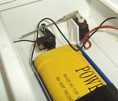
But I digress. The subject of this post is a tiny little thing. To be precise a micro servo.
I have plenty of spare standard size servos. More than I thought actually as I found some more in a box of parts intended for another model recently. Therefore when buying the bits for the new boat I didn’t think I needed to buy any more. Then test fitting one in the hull it hit me that I was wrong. The task was like trying to park a caravan in a telephone box. No linkage imaginable however crazy, was going to get control anywhere a standard size servo would fit.
The instructions point out this and suggest a micro servo. I hadn’t actually bothered to read this bit.
Howes supplied a micro device and a speed control (my spare one of these was too big as well) in a couple of days allowing me to build a little plasticard box from 2mm thick sheet. I had my doubts that something so small, and it really is tiny, would do the job but it does. Just like it’s big brother in fact. For around a quid over the cost of the normal version I can see a few more of these appearing on my bench – well worth the money.
Incidentally, don’t those bits making up the linkage look good. My first boats suffered from bent bits of wire until the discovery that a few quid bought the parts for a proper adjustable engineering job. Just like real model makers would do !
So, while I am fixing the damage on Flockburgh, here is something I did a few days ago. In case you are interested, the replacement bargeboards are fixed to the building and I’m fiddling with the computer while I let them dry. A bit of sanding is required and it’s never clever to sand plastic that has Mek-Pak on the surface since it’s not solid enough. There is a better chance of sticking the sandpaper to the plastic than smoothing anything.
But I digress. The subject of this post is a tiny little thing. To be precise a micro servo.
I have plenty of spare standard size servos. More than I thought actually as I found some more in a box of parts intended for another model recently. Therefore when buying the bits for the new boat I didn’t think I needed to buy any more. Then test fitting one in the hull it hit me that I was wrong. The task was like trying to park a caravan in a telephone box. No linkage imaginable however crazy, was going to get control anywhere a standard size servo would fit.
The instructions point out this and suggest a micro servo. I hadn’t actually bothered to read this bit.
Howes supplied a micro device and a speed control (my spare one of these was too big as well) in a couple of days allowing me to build a little plasticard box from 2mm thick sheet. I had my doubts that something so small, and it really is tiny, would do the job but it does. Just like it’s big brother in fact. For around a quid over the cost of the normal version I can see a few more of these appearing on my bench – well worth the money.
Incidentally, don’t those bits making up the linkage look good. My first boats suffered from bent bits of wire until the discovery that a few quid bought the parts for a proper adjustable engineering job. Just like real model makers would do !
Friday, September 01, 2006
Awaking a layout from its summer slumber
Flockburgh is due out at an exhibition in a couple of weeks. On top of this, next week it will be under the lens of the British Railway Modelling photographer. This weekend is therefore the time to get the layout out and make sure everything is up to scratch.
I hate turning up at a show and trying to fix a fault. Too many people seem to consider sorting out electrical glitches or major track problems to be part of the process of arriving at a show. I prefer to get set up and then clear off to the accommodation or pub. On the day itself people have paid to see trains move and that’s what I want to provide. There will always be occasions when something fails in service but if you start with a working model then some crossed fingers and touched wood ought to mean a trouble free weekend.
First, the good news. After being set up, apart from one sticky point motor that quickly got better, everything worked. No dead spots, or dodgy points. All the locomotives were fine except the Y7 which has always played up. Even that improved after a few minutes pickup tweaking.
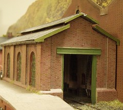
The only problem was some slight damage to the top of the engine shed. A couple of people and the water crane had come loose - nothing a touch of glue won’t solve. If it weren’t for the photographs I’d probably just bodge the shed top with a bit of paint, but the evil eye of the camera means a better repair is called for so this board is sat on the workbench for attention. I’ve already tried to remove the barge board but when the shed was built it was stuck in place properly so a bit of care and a nice sharp blade are called for.
I hate turning up at a show and trying to fix a fault. Too many people seem to consider sorting out electrical glitches or major track problems to be part of the process of arriving at a show. I prefer to get set up and then clear off to the accommodation or pub. On the day itself people have paid to see trains move and that’s what I want to provide. There will always be occasions when something fails in service but if you start with a working model then some crossed fingers and touched wood ought to mean a trouble free weekend.
First, the good news. After being set up, apart from one sticky point motor that quickly got better, everything worked. No dead spots, or dodgy points. All the locomotives were fine except the Y7 which has always played up. Even that improved after a few minutes pickup tweaking.
The only problem was some slight damage to the top of the engine shed. A couple of people and the water crane had come loose - nothing a touch of glue won’t solve. If it weren’t for the photographs I’d probably just bodge the shed top with a bit of paint, but the evil eye of the camera means a better repair is called for so this board is sat on the workbench for attention. I’ve already tried to remove the barge board but when the shed was built it was stuck in place properly so a bit of care and a nice sharp blade are called for.
Thursday, August 31, 2006
Matt Black Day
The BBC reports that Humbrol has gone into administration. This is VERY bad news and not just because it means another delay to the promised Severn Lifeboat kit.
While the media have focused on the plight of Airfix – mostly by banging on about kids making Lancaster bombers – I suspect that another manufacturer will quickly snap up this part of the brand. Let’s face it, you don’t get a more iconic name in the world of plastic kits than Airfix. Everyone remembers having a go at something they produced at one time. Even the BBC 6 o’clock news managed to find itself with three presenters on screen at the same time (including the female lead – shock horror, girls can make plastic kits) after veering toward the anorak stereotype in the report.
My worry is Humbrol’s excellent range of paint. No-one makes better enamel colour. Revell’s is thin and watery. Other makes tend to lack pigment and come in annoying screw top jars that jam is you forget to wipe the lips before putting the cap back on. They also cost more and are harder to get your hands on.
This calls for panic buying and stockpiling of supplies. I want to give the market time to get the product back on the shelf without having to hunt for a different makers product. Tinlets will be laid down in the manner of fine wines immediately. One day we might be saying, “It’s a cheeky Midland Maroon. 2006 vintage – a very good year.”
All this is the fault of the French. When Heller, another Humbrol company, went bust it refused to hand back the moulds which caused cash flow problems for the parent group. I think that this alone should cause the government to explain to the French Ambassador why we are breaking of diplomatic relations. All French markets, bread and stripy T-shirts must be made illegal at once. Sinking a great British company (Humbrol is a contraction of the full company name Humber Oil) is about as close to an act of war as you get without actually shelling the white cliffs of Dover.
While the media have focused on the plight of Airfix – mostly by banging on about kids making Lancaster bombers – I suspect that another manufacturer will quickly snap up this part of the brand. Let’s face it, you don’t get a more iconic name in the world of plastic kits than Airfix. Everyone remembers having a go at something they produced at one time. Even the BBC 6 o’clock news managed to find itself with three presenters on screen at the same time (including the female lead – shock horror, girls can make plastic kits) after veering toward the anorak stereotype in the report.
My worry is Humbrol’s excellent range of paint. No-one makes better enamel colour. Revell’s is thin and watery. Other makes tend to lack pigment and come in annoying screw top jars that jam is you forget to wipe the lips before putting the cap back on. They also cost more and are harder to get your hands on.
This calls for panic buying and stockpiling of supplies. I want to give the market time to get the product back on the shelf without having to hunt for a different makers product. Tinlets will be laid down in the manner of fine wines immediately. One day we might be saying, “It’s a cheeky Midland Maroon. 2006 vintage – a very good year.”
All this is the fault of the French. When Heller, another Humbrol company, went bust it refused to hand back the moulds which caused cash flow problems for the parent group. I think that this alone should cause the government to explain to the French Ambassador why we are breaking of diplomatic relations. All French markets, bread and stripy T-shirts must be made illegal at once. Sinking a great British company (Humbrol is a contraction of the full company name Humber Oil) is about as close to an act of war as you get without actually shelling the white cliffs of Dover.
Tuesday, August 29, 2006
Stand by your boat
OK, my last post wasn’t really accurate. Before you start drilling holes in the hull of a new model boat, you are supposed to make a stand for it. This stops it wobbling around and makes fitting out so much easier.
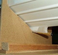
My Dad makes the boat stands. He fiddles around with card templates and then, in this case thin MDF found in the garage, to produce a nice support for my model.
I might try and argue that you can’t finish the stand until the propeller tube is in place because this will affect the shape of the cut-out but the instructions neglect to mention this.
Anyway, the boat in the air and stable you can see the prop tube in all it’s glory. Once I had tacked it into place with superglue, loads of car filler was gobbed around to restore water-tightness. This was a real mess but once dry a big file and some emery paper made for a nice neat job. And a load of dust.
My Dad makes the boat stands. He fiddles around with card templates and then, in this case thin MDF found in the garage, to produce a nice support for my model.
I might try and argue that you can’t finish the stand until the propeller tube is in place because this will affect the shape of the cut-out but the instructions neglect to mention this.
Anyway, the boat in the air and stable you can see the prop tube in all it’s glory. Once I had tacked it into place with superglue, loads of car filler was gobbed around to restore water-tightness. This was a real mess but once dry a big file and some emery paper made for a nice neat job. And a load of dust.
Sunday, August 27, 2006
As one box closes, another box opens
Time for another project. I know I have several on the go at present but this is a hobby and so I get to work on the things I like when I like and if you have any complaints about this I’ll see you outside. You have to let things dry and the only way I can do this at times is to go away and do something else. Manys the model I have made a less than perfect job of because I wouldn’t leave it alone to dry.
Anyway, the new entry onto the workbench is a George Turner Models launch. In theory this is a quick kit to build thanks to the construction being a series of vac-formed mouldings. Many model boat kits are like this, which means I have had to deal with a plastic kit format not seen in the model railway world.
The resulting model boat ought to be a very pleasant size to take to the lake. At a eighteen inches long I can tuck it under my arm but it is large enough to look sensible on the water. How builders of huge boats manage with their monsters is beyond me. Pigeon Pie is quite big enough and the magazines describe it as a “small boat”. This must make my new model a miniature !
First job on any boat (OK, boat kit with a plastic or GRP tub) is to take the nice waterproof hull and drill holes in it. Obviously this isn’t a good thing for its buoyancy so these have to be plugged with a drive shaft and rudder tube.
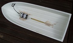
Lining up the drive shaft and motor was fun. I glued the shaft in, first with superglue and then with car body filler. The motor was then attached with a bit of plastic tube drilled to take propshaft and motor shaft. This placed the motor (in its mounting cradle) in the right position. Gobs of car filler then fixed this.
Then I left it alone to dry.
Anyway, the new entry onto the workbench is a George Turner Models launch. In theory this is a quick kit to build thanks to the construction being a series of vac-formed mouldings. Many model boat kits are like this, which means I have had to deal with a plastic kit format not seen in the model railway world.
The resulting model boat ought to be a very pleasant size to take to the lake. At a eighteen inches long I can tuck it under my arm but it is large enough to look sensible on the water. How builders of huge boats manage with their monsters is beyond me. Pigeon Pie is quite big enough and the magazines describe it as a “small boat”. This must make my new model a miniature !
First job on any boat (OK, boat kit with a plastic or GRP tub) is to take the nice waterproof hull and drill holes in it. Obviously this isn’t a good thing for its buoyancy so these have to be plugged with a drive shaft and rudder tube.
Lining up the drive shaft and motor was fun. I glued the shaft in, first with superglue and then with car body filler. The motor was then attached with a bit of plastic tube drilled to take propshaft and motor shaft. This placed the motor (in its mounting cradle) in the right position. Gobs of car filler then fixed this.
Then I left it alone to dry.
Thursday, August 24, 2006
Cruel Camera
The camera lens can be unforgiving as many modellers have found to their cost. Those wonky lines and iffy paintwork you see, and probably laugh at, in the magazines often aren’t apparent to the naked eye.
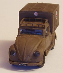
So it is with my finished VW. Until I looked at the photo I hadn’t spotted the thin layer of dust covering the paint. The dust is there because the model was sat on the workbench while I was vigorously sanding some filler on another project (watch this space for more details). The bits are really tiny and of course I hadn’t looked properly.
The model has turned out OK. Not a showpiece job in any sense but fun to do. The Polish mouldings aren’t as crisp as we’d expect from a UK or US plastic car kit. Some of the part fitting was a bit iffy too but nothing that a little filler can’t sure. Fortunately the prototype would have been a bit rough so the end result is reasonably realistic.
I’m quite pleased with the headlights. Many people use jewels or silver paint but looking at real car headlights when they are switched off, they are quite dark. I coloured the back of the lenses with black marker pen and stuck them in place. Still shinny but dark. Possibly a bit too dark – maybe a dark grey rather than back would have been better.
So it is with my finished VW. Until I looked at the photo I hadn’t spotted the thin layer of dust covering the paint. The dust is there because the model was sat on the workbench while I was vigorously sanding some filler on another project (watch this space for more details). The bits are really tiny and of course I hadn’t looked properly.
The model has turned out OK. Not a showpiece job in any sense but fun to do. The Polish mouldings aren’t as crisp as we’d expect from a UK or US plastic car kit. Some of the part fitting was a bit iffy too but nothing that a little filler can’t sure. Fortunately the prototype would have been a bit rough so the end result is reasonably realistic.
I’m quite pleased with the headlights. Many people use jewels or silver paint but looking at real car headlights when they are switched off, they are quite dark. I coloured the back of the lenses with black marker pen and stuck them in place. Still shinny but dark. Possibly a bit too dark – maybe a dark grey rather than back would have been better.
Wednesday, August 23, 2006
Pretty face
The Merchant Navy Locomotive is very, very nearly finished with only a couple of minor details to attend to. On the tender the light lenses need painting in and the model has to go through its paces again on the club layout. It certainly looks better than the slightly battered example I started with.
The front coupling is good and strong although I doubt it needs to be as I express locomotives never hauled much in reverse. Behind the buffer beam the hook is held on with a spring and bit of wire through the shank. Since the spring had long since vanished I had to replace it with one from a ballpoint pen suitably shortened. You would get a full locomotive set from one pen, which is probably cheaper than buying them from coupling manufacturers !
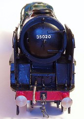
The front coupling is good and strong although I doubt it needs to be as I express locomotives never hauled much in reverse. Behind the buffer beam the hook is held on with a spring and bit of wire through the shank. Since the spring had long since vanished I had to replace it with one from a ballpoint pen suitably shortened. You would get a full locomotive set from one pen, which is probably cheaper than buying them from coupling manufacturers !
Monday, August 21, 2006
Plates
Heading toward the finishing post with the MN, I need to refurbish the nameplates.
The plates are etched brass and had tarnished over the years. Rubbing the surface with a very fine jewellers sanding stick – a pink one if this helps – burnished the brass. Using the stick means that I didn’t remove the paint that is a danger if you just use your finger. Also the abrasive is very, very fine, rough paper feels bumpier to the finger.
A quick coat of gloss varnish should seal the shine in for a while now. I touched up the blue centre s as well. These should have a pair of flags in but I haven’t a clue where to source the transfers. If I could find a good clear colour picture I might be tempted to paint them in by hand but for the moment I leave them blank. Sometimes not doing a job is better than doing it badly.
The front numberplates were more fun. They had the wrong background and had to be painted black. Then the numerals were picked out in white. The black was touched up where the white had spilled over. The white was re-done in places where it wasn’t quite right. Then the black was touched up again. I wish they were brass colour – I could “paint” this with sandpaper !
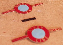
The plates are etched brass and had tarnished over the years. Rubbing the surface with a very fine jewellers sanding stick – a pink one if this helps – burnished the brass. Using the stick means that I didn’t remove the paint that is a danger if you just use your finger. Also the abrasive is very, very fine, rough paper feels bumpier to the finger.
A quick coat of gloss varnish should seal the shine in for a while now. I touched up the blue centre s as well. These should have a pair of flags in but I haven’t a clue where to source the transfers. If I could find a good clear colour picture I might be tempted to paint them in by hand but for the moment I leave them blank. Sometimes not doing a job is better than doing it badly.
The front numberplates were more fun. They had the wrong background and had to be painted black. Then the numerals were picked out in white. The black was touched up where the white had spilled over. The white was re-done in places where it wasn’t quite right. Then the black was touched up again. I wish they were brass colour – I could “paint” this with sandpaper !
Sunday, August 20, 2006
I Am Very, Very, Stupid.
This entry was nearly entitled “I Am A Very Dead Person”. Very nearly indeed.
The artfully cropped picture shows a newly fitted lampshade. Bought at a sale today, it appears to be an Art Deco piece. The glass shade attaches to a metal base. It looks good and fulfils a need for an enclosed bulb in the room. All the modern lampshades I’ve seen haven’t appealed as much as this one does and I’ve looked at a lot of them.
Buying lampshades doesn’t kill you though, fitting them can.
The old pendant lamp is interesting in that it has two switches. One on the wall by the door and one hanging from the ceiling on the other side of the room. Remove the old rose and fit the new one - easy.
Since I am by nature a careful person I switched the light on and then off again to make sure there was no power in the wires. Then I unscrewed the cover on the rose. Inside there were lots of wires. Three red ones connected together and three black ones. Two of the later connected to one wire on the bulb and the other went to complete the circuit on the other side. Obviously the electrician had been playing fast and lose with the colours when he wired the house.
This isn’t good but it didn’t seem too difficult to work out. When I replaced the fitting the three red wires get connected together in a chocolate block and the black wires go into the connection for the bulb.
It was when I disconnected the third red wire that it hit me. Literally. A nasty electric shock that made me make a hell of a loud noise. Despite my care I’d not bothered turning off the electricity to the house lights and one of the wires was still live thanks to the weird wiring. I only touched the wire for a fraction of a second and yet felt the tremors in my arm. Despite standing on a 2 foot tall wooden stool in thick rubber soled shoes on a wooden floor I had nearly electrocuted myself.
There is still the chance of brain damage thanks to be beating myself on the head for being so stupid. No more basic a rule for working with electricity exists than - Turn It Off When Fiddling.
Finished and working, my light looks really nice. Pity it was nearly so expensive.

The artfully cropped picture shows a newly fitted lampshade. Bought at a sale today, it appears to be an Art Deco piece. The glass shade attaches to a metal base. It looks good and fulfils a need for an enclosed bulb in the room. All the modern lampshades I’ve seen haven’t appealed as much as this one does and I’ve looked at a lot of them.
Buying lampshades doesn’t kill you though, fitting them can.
The old pendant lamp is interesting in that it has two switches. One on the wall by the door and one hanging from the ceiling on the other side of the room. Remove the old rose and fit the new one - easy.
Since I am by nature a careful person I switched the light on and then off again to make sure there was no power in the wires. Then I unscrewed the cover on the rose. Inside there were lots of wires. Three red ones connected together and three black ones. Two of the later connected to one wire on the bulb and the other went to complete the circuit on the other side. Obviously the electrician had been playing fast and lose with the colours when he wired the house.
This isn’t good but it didn’t seem too difficult to work out. When I replaced the fitting the three red wires get connected together in a chocolate block and the black wires go into the connection for the bulb.
It was when I disconnected the third red wire that it hit me. Literally. A nasty electric shock that made me make a hell of a loud noise. Despite my care I’d not bothered turning off the electricity to the house lights and one of the wires was still live thanks to the weird wiring. I only touched the wire for a fraction of a second and yet felt the tremors in my arm. Despite standing on a 2 foot tall wooden stool in thick rubber soled shoes on a wooden floor I had nearly electrocuted myself.
There is still the chance of brain damage thanks to be beating myself on the head for being so stupid. No more basic a rule for working with electricity exists than - Turn It Off When Fiddling.
Finished and working, my light looks really nice. Pity it was nearly so expensive.
Saturday, August 19, 2006
Windows
If you want a detail that says “unfinished model”, try leaving windows unglazed. Even though we are talking about a transparent substance, its absence marks a model down, at least in my eyes.
The Merchant Navy locomotive is nearing completion (I screwed it together properly today) and one of the jobs I had promised to do was fill in the windows.
While I could spend hours cutting out clear bits of plastic or glass, I have got better things to do. The results, when I do it anyway, always look hopeless. The glazing never fits properly and whatever glue I use is always visible at the edges. The first time the model is handled they all get pushed in anyway.
So I cheat and use Krystal Klear. Applied with screwdrivers, a skin is formed in the opening with the liquid (a high quality PVA) and then the model is left to dry with the window as horizontal as possible. Anything else gives a thicker pane at the bottom than the top.
Of course it does dry transparent, slightly flexible and quite reflective – as you can tell from my photo !
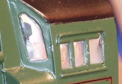
The Merchant Navy locomotive is nearing completion (I screwed it together properly today) and one of the jobs I had promised to do was fill in the windows.
While I could spend hours cutting out clear bits of plastic or glass, I have got better things to do. The results, when I do it anyway, always look hopeless. The glazing never fits properly and whatever glue I use is always visible at the edges. The first time the model is handled they all get pushed in anyway.
So I cheat and use Krystal Klear. Applied with screwdrivers, a skin is formed in the opening with the liquid (a high quality PVA) and then the model is left to dry with the window as horizontal as possible. Anything else gives a thicker pane at the bottom than the top.
Of course it does dry transparent, slightly flexible and quite reflective – as you can tell from my photo !
Friday, August 18, 2006
Gratification
It helps if the model goes together well. Building a kit that doesn’t fit together has the opposite effect and is likely to result in the parts being thrown in the direction of the nearest wall !
Anyway, I started a plastic kit. Plastic kits fit nicely into the role of quick, satisfying task. In theory all you do is cut out the bits and stick them together. Of course I had to pick a kit that needed a bit more work than this. A Polish model of the rare Volkswagen Type 93.
The prototype was built during the war as an adaptation of the famous Beetle. This hadn’t actually gone into full production when the war started but the factory was responsible for a number of German military vehicles. The logic of building a small van based largely on the bodyshell which the presses already existed for. Strangely the design wasn’t perpetuated after the conflict. When VW produced a small van they made a completely new design based on the Ghia chassis, the Fridolin.
The kit is from “Military Wheels” range and cost £5.99 from Gee Dee models of Nottingham. It’s not expensive but that shows in the quality of the parts. Flash, the like of which I haven’t seen for years is all over the place. It’s not difficult to remove but would be a challenge for a novice. The plastic is a bit softer than we are used to as well.
That said, the kit fits together OK and a couple of hours after I opened the box the model was as you see in the photo. I’d had a relaxing evening and the box isn’t going to make it into the store cupboard.
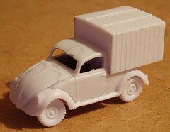
Anyway, I started a plastic kit. Plastic kits fit nicely into the role of quick, satisfying task. In theory all you do is cut out the bits and stick them together. Of course I had to pick a kit that needed a bit more work than this. A Polish model of the rare Volkswagen Type 93.
The prototype was built during the war as an adaptation of the famous Beetle. This hadn’t actually gone into full production when the war started but the factory was responsible for a number of German military vehicles. The logic of building a small van based largely on the bodyshell which the presses already existed for. Strangely the design wasn’t perpetuated after the conflict. When VW produced a small van they made a completely new design based on the Ghia chassis, the Fridolin.
The kit is from “Military Wheels” range and cost £5.99 from Gee Dee models of Nottingham. It’s not expensive but that shows in the quality of the parts. Flash, the like of which I haven’t seen for years is all over the place. It’s not difficult to remove but would be a challenge for a novice. The plastic is a bit softer than we are used to as well.
That said, the kit fits together OK and a couple of hours after I opened the box the model was as you see in the photo. I’d had a relaxing evening and the box isn’t going to make it into the store cupboard.
Wednesday, August 16, 2006
Satin
Paint can make or break a model. The Merchant Navy has reached the stage where it needs the paint tidying up. I’ve had to patch a few green bits but the black parts were the worst.
Fortunately black takes patching well and you can’t see all of the joins – Humbrol satin black goes on really nicely with a brush. Once this was done I cleaned the loco up and gave it a quick spray of satin varnish to brighten things up. It was a real transformation with the colour coming alive again.
Time to touch up the chassis matt black and then screw the thing together properly now.

Fortunately black takes patching well and you can’t see all of the joins – Humbrol satin black goes on really nicely with a brush. Once this was done I cleaned the loco up and gave it a quick spray of satin varnish to brighten things up. It was a real transformation with the colour coming alive again.
Time to touch up the chassis matt black and then screw the thing together properly now.
Tuesday, August 15, 2006
Everyone loves a bargain
While most people visit a car boot sale looking for a bargain that will appear on the antiques roadshow, there are lots of other bargains to be found. Just stop looking at the china.
People clearing out garages are fertile ground for the modeller. The photo shows just such a bargain that I nabbed last week. It’s a big reel of 0.5mm copper wire.
50p
How great is that ? Years worth of electrical droppers or even beading wire in the larger scales.
Of course get too much of this stuff and you need to clear out your workshop, which means a trip to the local car boot with your own stuff..

People clearing out garages are fertile ground for the modeller. The photo shows just such a bargain that I nabbed last week. It’s a big reel of 0.5mm copper wire.
50p
How great is that ? Years worth of electrical droppers or even beading wire in the larger scales.
Of course get too much of this stuff and you need to clear out your workshop, which means a trip to the local car boot with your own stuff..
Sunday, August 13, 2006
Pipes
This was an easier job than I expected. The old pipework at the bottom of the cylinders was missing on one side and mangled on the other.
Fortunately it was reasonably easy to pull out with pliers – a level of brut force and ignorance that most people won’t employ for fear of damaging something.
I had to replace one nut and then use 0.7mm wire for the pipes. This was soldered to the nuts and also to the other pipes to strengthen things. These bits are pretty vulnerable on the loco. A good clean up with the fibreglass pen and you can’t really see the joins.
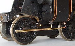
Fortunately it was reasonably easy to pull out with pliers – a level of brut force and ignorance that most people won’t employ for fear of damaging something.
I had to replace one nut and then use 0.7mm wire for the pipes. This was soldered to the nuts and also to the other pipes to strengthen things. These bits are pretty vulnerable on the loco. A good clean up with the fibreglass pen and you can’t really see the joins.
Squires
What this country needs is national service, sorry I mean lots more model shops. There should be one on every corner. Each to be fully stocked with a comprehensive range of tools and kits. No one should ever be more than 5 minutes walk from a tool for cutting plasticard.
Until that happy day arrives we have to reply on a few specialist shops and mail order. I’m lucky, there are good shops within 5 miles of my home. Two railway shops, one for radio control cars and another covering aircraft.
Of course, none can compete with a good mail order supplier for the supply of specialist tools. The market simply isn’t big enough locally. Cover the country, or better still the world and your sales might be enough to feed and clothe your children.
This entry is basically a plug for the excellent service provided by Squires Model & Craft Tools of Bognor Regis.
Yet again this week they can through with some clamps I need. A quick ‘phone call to 01243 842424 at lunchtime resulted in a parcel the next morning. I think that over a couple of dozen orders placed there has been only one occasion when the goods didn’t turn up the next day and then they were in my hands the day after. The service is superb, they know their range and can help you out if you aren’t sure what you need.
The stand at exhibitions has to be seen to be believed. A cornucopia of delights. Better still, if you buy anything the question, “Have you got our latest catalogue ? “ is always asked. This is free and yet is a vital resource for any modeller. It can eat your time though – hundreds of pages to tempt you. Simply browsing through out of interest takes several hours.
So if you haven’t got this publication, get on the ‘phone (no website and they don’t need one) and order your free copy. You’ll thank me later !
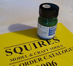
Until that happy day arrives we have to reply on a few specialist shops and mail order. I’m lucky, there are good shops within 5 miles of my home. Two railway shops, one for radio control cars and another covering aircraft.
Of course, none can compete with a good mail order supplier for the supply of specialist tools. The market simply isn’t big enough locally. Cover the country, or better still the world and your sales might be enough to feed and clothe your children.
This entry is basically a plug for the excellent service provided by Squires Model & Craft Tools of Bognor Regis.
Yet again this week they can through with some clamps I need. A quick ‘phone call to 01243 842424 at lunchtime resulted in a parcel the next morning. I think that over a couple of dozen orders placed there has been only one occasion when the goods didn’t turn up the next day and then they were in my hands the day after. The service is superb, they know their range and can help you out if you aren’t sure what you need.
The stand at exhibitions has to be seen to be believed. A cornucopia of delights. Better still, if you buy anything the question, “Have you got our latest catalogue ? “ is always asked. This is free and yet is a vital resource for any modeller. It can eat your time though – hundreds of pages to tempt you. Simply browsing through out of interest takes several hours.
So if you haven’t got this publication, get on the ‘phone (no website and they don’t need one) and order your free copy. You’ll thank me later !
Saturday, August 12, 2006
Buffers
One of the signs that the Merchant Navy needed a bit of tidying up was that its front buffer beam was a separate item. Not just that, it consists of a flat plate which has two buffers, a wonky vacuum pipe and some mangled strip attached to it.
The mangled mess at the ends was the front steps. On this locomotive they are unusual in that they are attached to the beam and the buffers instead of the more normal footplate. A fair bit of unbending gave me something that looked right. Once the intermediate steps were added from spare etch leftovers everything looked OK.
The very nice vac. pipe was straightened easily enough. All I had to do was re-fit the beam on the body.
A 7mm scale express locomotive is a pretty big beast. This means a large mass of metal. Soldering a thin bufferbeam to this required heat from a small blowtorch. The paint you see in the picture was red before I started burning it. And when I’d raised the temperature enough for the solder to run – the steps unsoldered themselves and the vac. pipe went wonky again.
The moral of this story is – attach the little bits to big bits one at a time. If you must have a subassembly , bolt it or glue it to the other sub assemblies.
Still, at least the buffers etc. were tinned (covered in leftover solder) and the re-attachment wasn’t too bad. With front buffers the loco is now looking a lot better. Since the photo I’ve primed the metal with car touch up paint pots. Once this is dry I’ll dig out the red paint.
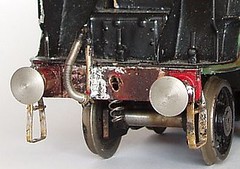
The mangled mess at the ends was the front steps. On this locomotive they are unusual in that they are attached to the beam and the buffers instead of the more normal footplate. A fair bit of unbending gave me something that looked right. Once the intermediate steps were added from spare etch leftovers everything looked OK.
The very nice vac. pipe was straightened easily enough. All I had to do was re-fit the beam on the body.
A 7mm scale express locomotive is a pretty big beast. This means a large mass of metal. Soldering a thin bufferbeam to this required heat from a small blowtorch. The paint you see in the picture was red before I started burning it. And when I’d raised the temperature enough for the solder to run – the steps unsoldered themselves and the vac. pipe went wonky again.
The moral of this story is – attach the little bits to big bits one at a time. If you must have a subassembly , bolt it or glue it to the other sub assemblies.
Still, at least the buffers etc. were tinned (covered in leftover solder) and the re-attachment wasn’t too bad. With front buffers the loco is now looking a lot better. Since the photo I’ve primed the metal with car touch up paint pots. Once this is dry I’ll dig out the red paint.
Friday, August 11, 2006
On the right track
One of the benefits of belonging to a model railway club is the chance to test a locomotive on a layout without the effort of building one. OK, you might join in the team but it’s always going to be less work than going alone.
So it was very handy last night to be able to test the Navy chassis in our O gauge layout. While I was happy it worked in a straight line, real layouts have curves and points and even gradients. And this is a real layout.
It worked. There was the occasional spark but nothing that I can’t fix easily. The bogie needs a spring to push it onto the track harder than its weight alone does. But it works. We ran it around without derailments or any embarrassing incidents for me.
The audience approved as well. The downside of club modelling is that you can’t sneak a test like this without someone spotting. Half a dozen people made comments containing varying amounts of useful advice. One person looked at it and commented how he wished he could build a kit. This resulted in a quick run down of how easy kit building is and passing on a few hints and tips. That’s what club life is about, a bit of give and take.
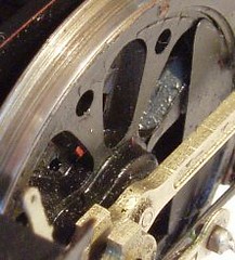
So it was very handy last night to be able to test the Navy chassis in our O gauge layout. While I was happy it worked in a straight line, real layouts have curves and points and even gradients. And this is a real layout.
It worked. There was the occasional spark but nothing that I can’t fix easily. The bogie needs a spring to push it onto the track harder than its weight alone does. But it works. We ran it around without derailments or any embarrassing incidents for me.
The audience approved as well. The downside of club modelling is that you can’t sneak a test like this without someone spotting. Half a dozen people made comments containing varying amounts of useful advice. One person looked at it and commented how he wished he could build a kit. This resulted in a quick run down of how easy kit building is and passing on a few hints and tips. That’s what club life is about, a bit of give and take.
Wednesday, August 09, 2006
Twelve wheels on my ..er.. loco.
The biggest problem with the Merchant Navy Locomotive was that the front bogie wasn’t attached to the chassis. What was worse was that it appeared never to have been attached to the chassis.
This has puzzled me for a while. Why finish the model as far as painting and not complete the chassis so it can run on your model railway ? The answer wouldn’t have helped of course. What I needed to do was rectify the problem.
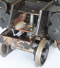
Now there is a hole above the place the bogie should be but it’s very high and too small for anything that you’d want controlling O gauge wheels. After a bit of playing around I worked out that a largish (M4 I think) bolt would fit reasonably well. Since the bogie stretcher has a slot in it I needed to bush this. Digging in the bush pot I found what may be a 7mm scale axle bush. This fitted the bolt and was slightly too large for the slot. Opening out the later with a file cured this.
The plate the nut is attached to came from some leftover brass from the G2. Always hang on to useful bits left over from kits as they are very handy. Just don’t forget to turn those empty frets into strips or you will quickly find your work area taken over by them !
Yet again I couldn’t solder to the frames. They are 2mm thick brass and despite my best efforts with a mini blowtorch, no solder will stick as I couldn’t get the metal hot enough. If the whitemetal cylinders weren’t attached I might have been more courageous but I really didn’t want to have to replace these. Because of this, some nice thick Araldite hold it in place. Unfashionable though this method is – it works.
After letting the glue dry I was able to run the model on the test track – a 6ft straight. The fireworks (sparks caused by short circuits) showed I needed to cut the frames away a bit or the loco wasn’t going around corners. More work with the big file, no good using needle files on this stuff, and the sparks stopped. I might find myself insulating the back of the front brake shoes with superglue just be extra sure.
This has puzzled me for a while. Why finish the model as far as painting and not complete the chassis so it can run on your model railway ? The answer wouldn’t have helped of course. What I needed to do was rectify the problem.
Now there is a hole above the place the bogie should be but it’s very high and too small for anything that you’d want controlling O gauge wheels. After a bit of playing around I worked out that a largish (M4 I think) bolt would fit reasonably well. Since the bogie stretcher has a slot in it I needed to bush this. Digging in the bush pot I found what may be a 7mm scale axle bush. This fitted the bolt and was slightly too large for the slot. Opening out the later with a file cured this.
The plate the nut is attached to came from some leftover brass from the G2. Always hang on to useful bits left over from kits as they are very handy. Just don’t forget to turn those empty frets into strips or you will quickly find your work area taken over by them !
Yet again I couldn’t solder to the frames. They are 2mm thick brass and despite my best efforts with a mini blowtorch, no solder will stick as I couldn’t get the metal hot enough. If the whitemetal cylinders weren’t attached I might have been more courageous but I really didn’t want to have to replace these. Because of this, some nice thick Araldite hold it in place. Unfashionable though this method is – it works.
After letting the glue dry I was able to run the model on the test track – a 6ft straight. The fireworks (sparks caused by short circuits) showed I needed to cut the frames away a bit or the loco wasn’t going around corners. More work with the big file, no good using needle files on this stuff, and the sparks stopped. I might find myself insulating the back of the front brake shoes with superglue just be extra sure.
Monday, August 07, 2006
Bad paper
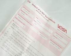
The MOT went pretty as mush as expected. I now posses a fail sheet listing various deficiencies. While the rear valance wasn’t an issue but the MOT man’s hammer found another area of rot that needs attention.
The main problems are brake related. I could do these, I’m sure of it. If only it were possible for me to get the van in the air to a comfortable height, a few hours work with spanners should see the job done. My rosy view will ignore the skinned knuckles and stuck bolts reality normally throws in the way.
Lifting the van would probably have averted the welding too. Lying on your back crawling around under a vehicle isn’t pleasant and certainly is not conducive to taking a proper look. The nooks and crannies are ignored to punish me for my laziness at this time of year.
It’s a very impotent feeling. I could so nearly do this work. I want to do the work. What I don’t want to do is fix one side and then have to bleed the brakes so I can turn the vehicle around to get at the other side – I have park next to a wall. Actually I don’t want to be working in the blazing sun either. Lying under the axle and welding doesn’t sound too fun either – setting myself on fire is more likely than achieving a proper fix.
I imagine it’s like being a newbie model maker. You look at people like me with a reasonably equipped toolbox and think, “it’s easy for them, they have all the kit.”. Truth is that I acquired tools in dribs and drabs over a long period. Mostly they come as solutions to problems, or at least as ways of making the job easier. A good example is the box of reamers and cutting broaches. You can manage with a needle file but the right tools are so much nicer.
So I look at those with good size garage and some sort of lifting facility and envy them. I know they too have built a workshop up over years – indeed a proper workshop should have some very old but very usable tools, preferably from a long closed garage.
In the meantime I will contract the work out to someone for whom getting a one ton van in the air is easy. Someone who has done the job before and probably won’t bruise his knuckles as badly as I would. He won’t lavish the care I would like to think I would, cleaning and greasing every part, perhaps even painting stuff that has surface rust, but then I do get the chance to spend time doing things I enjoy. Perhaps I am happier with the dream and the reality wouldn’t be as good as I expect. Just like the newbies envying the modelling I do don’t see the burns and frustration when bits don’t fit together on the latest expensive kit.
Of course if anyone HAS got a barn they would like to let me use…
The main problems are brake related. I could do these, I’m sure of it. If only it were possible for me to get the van in the air to a comfortable height, a few hours work with spanners should see the job done. My rosy view will ignore the skinned knuckles and stuck bolts reality normally throws in the way.
Lifting the van would probably have averted the welding too. Lying on your back crawling around under a vehicle isn’t pleasant and certainly is not conducive to taking a proper look. The nooks and crannies are ignored to punish me for my laziness at this time of year.
It’s a very impotent feeling. I could so nearly do this work. I want to do the work. What I don’t want to do is fix one side and then have to bleed the brakes so I can turn the vehicle around to get at the other side – I have park next to a wall. Actually I don’t want to be working in the blazing sun either. Lying under the axle and welding doesn’t sound too fun either – setting myself on fire is more likely than achieving a proper fix.
I imagine it’s like being a newbie model maker. You look at people like me with a reasonably equipped toolbox and think, “it’s easy for them, they have all the kit.”. Truth is that I acquired tools in dribs and drabs over a long period. Mostly they come as solutions to problems, or at least as ways of making the job easier. A good example is the box of reamers and cutting broaches. You can manage with a needle file but the right tools are so much nicer.
So I look at those with good size garage and some sort of lifting facility and envy them. I know they too have built a workshop up over years – indeed a proper workshop should have some very old but very usable tools, preferably from a long closed garage.
In the meantime I will contract the work out to someone for whom getting a one ton van in the air is easy. Someone who has done the job before and probably won’t bruise his knuckles as badly as I would. He won’t lavish the care I would like to think I would, cleaning and greasing every part, perhaps even painting stuff that has surface rust, but then I do get the chance to spend time doing things I enjoy. Perhaps I am happier with the dream and the reality wouldn’t be as good as I expect. Just like the newbies envying the modelling I do don’t see the burns and frustration when bits don’t fit together on the latest expensive kit.
Of course if anyone HAS got a barn they would like to let me use…
Sunday, August 06, 2006
The future is light up light switches
One of the benefits of all this model making is that I’m not bad at DIY jobs – or at least I’m not scared of them.
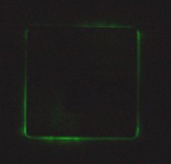
The Problem: The garage is dark and it’s difficult to find the light switch.
Solution: Fit a light switch glowing thing. Now I can find the switch easily !
Of course this was partly influenced by finding the glowey thing on a car boot table and thinking, “Wow, how fantastic is that, glowing light switches !”. Best fun I’ve had for 30p for a long while. Perhaps I need to get out more.
Technical note: The glowey thing is a plastic plate that fits behind the switch. It’s got two lamps in it and wires straight into the switch. It comes from MK but I’ve never seen one before. Bit fiddly to fit but worth the effort.
The Problem: The garage is dark and it’s difficult to find the light switch.
Solution: Fit a light switch glowing thing. Now I can find the switch easily !
Of course this was partly influenced by finding the glowey thing on a car boot table and thinking, “Wow, how fantastic is that, glowing light switches !”. Best fun I’ve had for 30p for a long while. Perhaps I need to get out more.
Technical note: The glowey thing is a plastic plate that fits behind the switch. It’s got two lamps in it and wires straight into the switch. It comes from MK but I’ve never seen one before. Bit fiddly to fit but worth the effort.
Saturday, August 05, 2006
Rotten, just rotten
Why is it that car jobs ALWAYS get worse not better when you approach them ?
The photo shows the state of the read valance on my Volkswagen Type 2 air-cooled campervan*
With the MOT approaching I thought I’d better start getting it ready. Two jobs were needed before it went for the first attempt – Adjust the brakes and bodge the rear valance.
Brakes. Oh dear. This is supposed to be an easy job. I’d done it on my Beetle in the past but hate it. I jacked the van up so the wheel was a little off the ground. The adjusters didn’t seem to want to move. Thinking better of crawling under the vehicle with it supported only by a jack I got the axle stands out. They aren’t quite tall enough as they are designed for a normal car, not something fat blokes can crawl under comfortably. Anyway, we have a gravel drive with slabs for driving on. No slab where I needed to put the stand though. Oh, well, I hate it anyway so someone who knows what they are doing can handle this one.
The valance. My idea had been to slap a patch over that little hole in it. I have the replacement part in the garage but reckon I need at least two full days to fit it. Of course when I saw this, the patch idea went out of the window. No chance of any days off work this month for me unfortunately.
Sooooo, my new plan is to take the van for it’s MOT on Monday. It will fail. Then take it around to Malc saying, “Get it through the MOT and take all my money.” And cry at the bill. Sometimes there aren’t enough hours in the day to do everything you want to do.
Next year can someone remind the MOT is due earlier than two weeks before it is please ?
*Yes I am writing a lot of keywords in the text. I need to make those Google adverts pay. Please click on them – it costs you nothing and makes me a few pence richer. How else am I to pay for these projects you enjoy reading about ? :-)
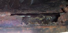
The photo shows the state of the read valance on my Volkswagen Type 2 air-cooled campervan*
With the MOT approaching I thought I’d better start getting it ready. Two jobs were needed before it went for the first attempt – Adjust the brakes and bodge the rear valance.
Brakes. Oh dear. This is supposed to be an easy job. I’d done it on my Beetle in the past but hate it. I jacked the van up so the wheel was a little off the ground. The adjusters didn’t seem to want to move. Thinking better of crawling under the vehicle with it supported only by a jack I got the axle stands out. They aren’t quite tall enough as they are designed for a normal car, not something fat blokes can crawl under comfortably. Anyway, we have a gravel drive with slabs for driving on. No slab where I needed to put the stand though. Oh, well, I hate it anyway so someone who knows what they are doing can handle this one.
The valance. My idea had been to slap a patch over that little hole in it. I have the replacement part in the garage but reckon I need at least two full days to fit it. Of course when I saw this, the patch idea went out of the window. No chance of any days off work this month for me unfortunately.
Sooooo, my new plan is to take the van for it’s MOT on Monday. It will fail. Then take it around to Malc saying, “Get it through the MOT and take all my money.” And cry at the bill. Sometimes there aren’t enough hours in the day to do everything you want to do.
Next year can someone remind the MOT is due earlier than two weeks before it is please ?
*Yes I am writing a lot of keywords in the text. I need to make those Google adverts pay. Please click on them – it costs you nothing and makes me a few pence richer. How else am I to pay for these projects you enjoy reading about ? :-)
Friday, August 04, 2006
Quick change on the workbench
With one project leaving the workbench, the space is quickly filled by another. This time I have a 7mm scale, O Gauge rebuilt Battle of Britain. The locomotive is complete, it just needs a little tidying up.
The first job was to have a good look and see what is needed. The most obvious work is with the chassis. Brake gear is loose, valve gear is bent and the paint needs a fair bit of TLC.
The brakes weren’t too bad. It was only the rear shoes flapping in the wind. Soldering didn’t work so some good strong glue did the job instead. With all the paint and dirt plus the mass of brass I was never going to get enough heat into the joint without damaging something. I did replace some wire which makes for a nice solid job.
The valve gear was straightened and then I took the time to fettle it a bit by removing some excess lumpy solder that was present in a few places. Valve gear is very important to the look of a locomotive. If it’s wobbly it looks wrong. On the prototype those rods are big think lumps of steel. Anything bent represented a Very Bad Thing.
Paining comes next, what’s there is lumpy and flaking off – the model has done some miles but with a bit of work it’s going to be ready for many more.
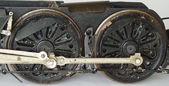
The first job was to have a good look and see what is needed. The most obvious work is with the chassis. Brake gear is loose, valve gear is bent and the paint needs a fair bit of TLC.
The brakes weren’t too bad. It was only the rear shoes flapping in the wind. Soldering didn’t work so some good strong glue did the job instead. With all the paint and dirt plus the mass of brass I was never going to get enough heat into the joint without damaging something. I did replace some wire which makes for a nice solid job.
The valve gear was straightened and then I took the time to fettle it a bit by removing some excess lumpy solder that was present in a few places. Valve gear is very important to the look of a locomotive. If it’s wobbly it looks wrong. On the prototype those rods are big think lumps of steel. Anything bent represented a Very Bad Thing.
Paining comes next, what’s there is lumpy and flaking off – the model has done some miles but with a bit of work it’s going to be ready for many more.
Wednesday, August 02, 2006
Of paintpots and teacakes
The photograph shows a 50ml tin of Humbrol matt black paint just before it went in the bin. As you can see there are lots of dried “tide marks” in it where the paint has formed skin and I’ve poked a stirrer through it to get at the liquid stuff.
50ml pots are a bit like Tunocks teacakes really.
Let me explain. I love a nice Tunnocks teacake. It’s a delicious pudding in a foil wrapper. Ideal - one is sufficient and not too calorific. When I finish chomping I sometimes think, “That was nice, I fancy another.”. Most of the time I resist but just occasionally I go for it. And then I regret it. You see the second teacake is nothing like as good as the first. I don’t know why, it just doesn’t satisfy in the same way.
50ml pots of paint are like this. Normally I realise I will end up throwing most of the pot away but every so often it seems like a good idea. After all I use a lot of matt black paint so surely it’s cheaper to buy in bulk ?
It never is though. Like the second teacake, the bigger pot never works like it supposed to. And I know I’ll never learn. That second teacake still seems like a good idea.
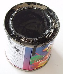
50ml pots are a bit like Tunocks teacakes really.
Let me explain. I love a nice Tunnocks teacake. It’s a delicious pudding in a foil wrapper. Ideal - one is sufficient and not too calorific. When I finish chomping I sometimes think, “That was nice, I fancy another.”. Most of the time I resist but just occasionally I go for it. And then I regret it. You see the second teacake is nothing like as good as the first. I don’t know why, it just doesn’t satisfy in the same way.
50ml pots of paint are like this. Normally I realise I will end up throwing most of the pot away but every so often it seems like a good idea. After all I use a lot of matt black paint so surely it’s cheaper to buy in bulk ?
It never is though. Like the second teacake, the bigger pot never works like it supposed to. And I know I’ll never learn. That second teacake still seems like a good idea.
Tuesday, August 01, 2006
OK, so I'm a big kid.
All breakfast cereal should be like this. Open the packet and out fall a plastic car. This one even has stickers you can decorate it with.
Those who keep their eyes open will be aware of the Disney film “Cars” is out now – this is “Doc Hudson” from the film, or in this case from a packet of Cherrios.
The makers (of the model not the ever litigious Disney) have pinched a trick from Dinky cars. There are a couple of light tubes from the roof to the headlights so they actually appear to light up. Ingenious. I’m always fascinated by the cost of tooling up for something like this. Someone has designed a set of moulds, made the parts and then assembled them. Somewhere in a factory, probably in China and paying pathetic wages, there are factories full of people making these things up.
Of course the cereal approach to modelling isn’t perfect. I want a “Filmore” but there isn’t one in a packet near me. Still, if all breakfast food included plastic model, surely the problem of people skipping breakfast would be ended. Mind you, the new issue would be people playing when they should be going to work…
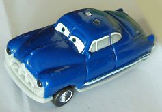
Those who keep their eyes open will be aware of the Disney film “Cars” is out now – this is “Doc Hudson” from the film, or in this case from a packet of Cherrios.
The makers (of the model not the ever litigious Disney) have pinched a trick from Dinky cars. There are a couple of light tubes from the roof to the headlights so they actually appear to light up. Ingenious. I’m always fascinated by the cost of tooling up for something like this. Someone has designed a set of moulds, made the parts and then assembled them. Somewhere in a factory, probably in China and paying pathetic wages, there are factories full of people making these things up.
Of course the cereal approach to modelling isn’t perfect. I want a “Filmore” but there isn’t one in a packet near me. Still, if all breakfast food included plastic model, surely the problem of people skipping breakfast would be ended. Mind you, the new issue would be people playing when they should be going to work…
Sunday, July 30, 2006
Finished
Hooray – I’ve finally finished something !
The HO scale Barclay is complete. The simple livery (can something so plain be said to have a livery ?) doesn’t take long to complete. I sprayed the black and hand painted the red buffer beams. Fortunately an ex-works finish wasn’t required otherwise the paint “bloom” on the cab sides would have been a problem. As it is, the weathered finish is enhanced by the slightly washed out effect.
The WD and arrow had to be hand painted as I’ve never managed to find a transfer for this. I wish I could as this must be the fifth time I have built this loco (2 static plastic attempts before plans were available and 3 kits). Chris has a lot to answer for with Overlord.
Once I complete a loco it spends along while running up and down the test rack on the workbench. Not to run it in as a rolling road does this better, but just because I like to see the source of fun and frustration actually work. It'’ like watching telly but the plot and characters are better. Very relaxing.
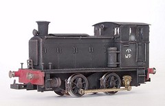
The HO scale Barclay is complete. The simple livery (can something so plain be said to have a livery ?) doesn’t take long to complete. I sprayed the black and hand painted the red buffer beams. Fortunately an ex-works finish wasn’t required otherwise the paint “bloom” on the cab sides would have been a problem. As it is, the weathered finish is enhanced by the slightly washed out effect.
The WD and arrow had to be hand painted as I’ve never managed to find a transfer for this. I wish I could as this must be the fifth time I have built this loco (2 static plastic attempts before plans were available and 3 kits). Chris has a lot to answer for with Overlord.
Once I complete a loco it spends along while running up and down the test rack on the workbench. Not to run it in as a rolling road does this better, but just because I like to see the source of fun and frustration actually work. It'’ like watching telly but the plot and characters are better. Very relaxing.
Saturday, July 29, 2006
A hole lot of work
You should always build a working chassis before making the body. If you don’t you can find yourself spending a Friday night hacking your way through bits of a complete body in order to get the motor in.
I started with a slitting disk as far up the sides of the bulkhead as I could. Then I tried burs and grinders to do the rest. Nothing really worked so I used some tin snips to cut the metal up a bit. The leftovers were then twisted and waggled with small pliers to break them off. Not too bad in the case of the bulkhead at the end of the bonnet – the soldered joint gave way eventually allowing the mostly complete piece to be removed. The cab front gave more of a struggle it came as well.
A little soldering where the top of the bonnet had become loose, some filing on the sides to tidy the hole up – yes that is the tidy hole on the photo - and the motor went in. Good job the cab is so enclosed that you can’t see the back end of Mashima where the controls should be !
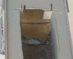
I started with a slitting disk as far up the sides of the bulkhead as I could. Then I tried burs and grinders to do the rest. Nothing really worked so I used some tin snips to cut the metal up a bit. The leftovers were then twisted and waggled with small pliers to break them off. Not too bad in the case of the bulkhead at the end of the bonnet – the soldered joint gave way eventually allowing the mostly complete piece to be removed. The cab front gave more of a struggle it came as well.
A little soldering where the top of the bonnet had become loose, some filing on the sides to tidy the hole up – yes that is the tidy hole on the photo - and the motor went in. Good job the cab is so enclosed that you can’t see the back end of Mashima where the controls should be !
LMS Railcar
Rooting around my local auction I was digging into a box of model railway tat and struck gold. Among the used Hornby buildings, broken O gauge Hornby and stuff there was this – a wooden OO model of an LMS 1930’s railcar.
Fortunately no one else showed any interest in the model although the second hand buildings in the lot had them looking and I was able to buy it for a price that should allow me to recoup my money from eBay.
The model fascinates me. It’s unfinished but is complete enough to appreciate the workmanship involved. As far as I know no kit was ever available for this prototype. The cleanness of the model making is astounding though. If the wooden sides weren’t die cut, how are the windows so square ? Curving the ends must also have been a challenge. I’m assuming the material was steamed otherwise it surly would have splintered.
Does anyone recognise this model ? Was it a kit ? If so, who produced it ?
I’ll still need to acquire bogies to finish the model – or cast some from the one currently attached.. Provision has been made for a motor bogie, which should by rights be a Tri-ang item. For the minute the model will be boxed up and put in the maturing cupboard. If I’m right it’s nearly 40 years old already so another few years won’t matter.
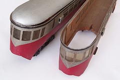
Fortunately no one else showed any interest in the model although the second hand buildings in the lot had them looking and I was able to buy it for a price that should allow me to recoup my money from eBay.
The model fascinates me. It’s unfinished but is complete enough to appreciate the workmanship involved. As far as I know no kit was ever available for this prototype. The cleanness of the model making is astounding though. If the wooden sides weren’t die cut, how are the windows so square ? Curving the ends must also have been a challenge. I’m assuming the material was steamed otherwise it surly would have splintered.
Does anyone recognise this model ? Was it a kit ? If so, who produced it ?
I’ll still need to acquire bogies to finish the model – or cast some from the one currently attached.. Provision has been made for a motor bogie, which should by rights be a Tri-ang item. For the minute the model will be boxed up and put in the maturing cupboard. If I’m right it’s nearly 40 years old already so another few years won’t matter.
Friday, July 28, 2006
Taller box
I have to confess that the last post to this blog was actually written a few days ago. Since then a quick ‘phone call has elicited the supply of a set of gears with the correct input shafts (1.5 not 2mm – it matters !) and a new taller gearbox.
The new box fitted fine once I’d removed the bit of paxolin intended to support the pick-ups. A word of advice here, if using Gibson wheels, check the axles. I managed to put the EM one in and start fitting the wheels before I noticed…
The cut outs in the chassis don’t need to be as big now but suprisingly they are still required. This motor is quite a chubby chap ! I still hope that under the footplate they don’t show up.
The rods and cranks were re-fitted and with a bit more fettling whirl round amazingly (for one of my chassis) smoothly. It was all a bit sticky before I oiled the axle with the cranks on though. A couple of drops and like magic, everything was fine. The effect was something I’ve never experienced, oil normally improves things but not instantly or as markedly.
One problem is that the motor now sits further back in the chassis. Which means it won’t go in the body because the cab front gets in the way. Grrrrrrrrrr.
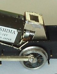
The new box fitted fine once I’d removed the bit of paxolin intended to support the pick-ups. A word of advice here, if using Gibson wheels, check the axles. I managed to put the EM one in and start fitting the wheels before I noticed…
The cut outs in the chassis don’t need to be as big now but suprisingly they are still required. This motor is quite a chubby chap ! I still hope that under the footplate they don’t show up.
The rods and cranks were re-fitted and with a bit more fettling whirl round amazingly (for one of my chassis) smoothly. It was all a bit sticky before I oiled the axle with the cranks on though. A couple of drops and like magic, everything was fine. The effect was something I’ve never experienced, oil normally improves things but not instantly or as markedly.
One problem is that the motor now sits further back in the chassis. Which means it won’t go in the body because the cab front gets in the way. Grrrrrrrrrr.
Thursday, July 27, 2006
In HO, no one can hear you scream
Thanks to a cock-up in the supply of gearsets, I find myself fitting a tiny gearbox into the HO Barclay. The ‘box took a fair bit of fettling, much more than is normal with these things, but I made it work OK.
Then I had to fit it in the chassis and a problem appeared. The motor was too chubby for the frames. If I’d been working in P4 there wouldn’t have been a problem this is a 3.5mm loco. A taller gearbox would also solve the problem but there wasn’t one handy.
Out came the tin snips and with a little fiddling I think I made quite a nice job. The cut outs look worse than they are as with the motor painted black you won’t really see anything under the footplate.
With the motor & gears fitted the loco ran very sweetly. Putting the rods on cured this but only after a small amount of bad language and reaming out of holes even this problem was removed.
Then the gears lost mesh. I’d not managed to get them as tight as I should have done. The only solution is to remove the wheels, and gears to adjust or replace the box. I’m not happy.
Then I had to fit it in the chassis and a problem appeared. The motor was too chubby for the frames. If I’d been working in P4 there wouldn’t have been a problem this is a 3.5mm loco. A taller gearbox would also solve the problem but there wasn’t one handy.
Out came the tin snips and with a little fiddling I think I made quite a nice job. The cut outs look worse than they are as with the motor painted black you won’t really see anything under the footplate.
With the motor & gears fitted the loco ran very sweetly. Putting the rods on cured this but only after a small amount of bad language and reaming out of holes even this problem was removed.
Then the gears lost mesh. I’d not managed to get them as tight as I should have done. The only solution is to remove the wheels, and gears to adjust or replace the box. I’m not happy.
Monday, July 24, 2006
Etched brass tender
With most of the castings in place, the tender is looking pretty good. The work left involves superglue and not solder. I like this stage as it takes me back to sticking Airfix kits together.
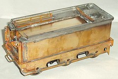
Sunday, July 23, 2006
Underneath the tender
Fitting the chassis to the tender body was always going to be an interesting task. Unlike most models, the tender is going to be carrying the fuel – in this case the batteries. I need as much space as possible to fit these in, which means not much in the bottom to get in the way.
Of course I still need to fix the chassis in place. Normally I use bolts but only one was in with the kit for this task. Possibly a mix up in the packing but in this case it’s forced me to be inventive and come up with a “clever” solution.
One end is screwed in place conventionally. The other tucks into a pocket behind the buffer beam. As well as being quicker to assemble (I will probably have this chassis on and off a fair bit), it leaves the maximum amount of hole in the floor so I can squeeze those cells in place.
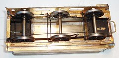
Of course I still need to fix the chassis in place. Normally I use bolts but only one was in with the kit for this task. Possibly a mix up in the packing but in this case it’s forced me to be inventive and come up with a “clever” solution.
One end is screwed in place conventionally. The other tucks into a pocket behind the buffer beam. As well as being quicker to assemble (I will probably have this chassis on and off a fair bit), it leaves the maximum amount of hole in the floor so I can squeeze those cells in place.
Flare Jigsaw
The tender flare for the G2 has been the cause of worry for me. I have two options: a set of whitemetal parts or a brass etched version.
The brass version looked promising except that the contact area between the top of the body and the brass flare would be tiny. This would make it weak. I’d also have to figure out how to do the rear corners.
This still looked better than the whitemetal version. I’ve looked at these parts for weeks and have struggled to work out how they work. The instructions are silent on the point, not mentioning the flare at all.
Of course my Dad picks the parts up and immediately sees what needs to happen. If you look at the photo it’s obvious – but I hadn’t spotted it for some reason. It cleverly includes the tender top – I’d been wondering why this wasn’t on the etch !
OK, the resulting part is too wide, but that was easy to fix but cutting and shutting. Low melt solder (still applied with a big iron) is a good filler and after some filing and sanding the result looks pretty good.
The brass version looked promising except that the contact area between the top of the body and the brass flare would be tiny. This would make it weak. I’d also have to figure out how to do the rear corners.
This still looked better than the whitemetal version. I’ve looked at these parts for weeks and have struggled to work out how they work. The instructions are silent on the point, not mentioning the flare at all.
Of course my Dad picks the parts up and immediately sees what needs to happen. If you look at the photo it’s obvious – but I hadn’t spotted it for some reason. It cleverly includes the tender top – I’d been wondering why this wasn’t on the etch !
OK, the resulting part is too wide, but that was easy to fix but cutting and shutting. Low melt solder (still applied with a big iron) is a good filler and after some filing and sanding the result looks pretty good.
Friday, July 21, 2006
Proper tools
When you are building high quality models, the mind automatically turns to thoughts of the toolkit commonly found in a jewellers workshop. Delicate little devices capable to assisting the finest of work.
Sometimes this kit isn’t enough though. For example I have always preferred a large file to a small one as it’s easier to file things flat as opposed to a series of small ridges. This was a trick suggested to me by a friend who had witnessed too many people messing around with needle files ‘cos that is what you are supposed to use. I now have three big files on the bench and the smallest is 8 inches long and half an inch wide. The needle files live in the packet most of the time.
Anyway, while fitting the chassis to the G2 I had to enlarge the holes in the spaces that take the bolts. This is a big loco so you use big bolts – simple really. Now the spacers are thick, solid brass and a needle files wouldn’t touch it. Neither would the tapered reamer.
So off to the garage to get the power drill. A Bosch rechargeable if you want to get anoraky about it. A few seconds work and I had a nice large hole in the spacer. Then I cleaned the edges with the countersink bit. Proper job.
Then the retaining nut wouldn’t fit under the footplate so there was the unedifying site of the loco being attacked with the drill as well. I’m sure this isn’t what those photos of proper “craftsmen” show.
It worked a treat though. Perhaps I should keep it within reach at all times. I wonder if a hammer drill would be useful too ?
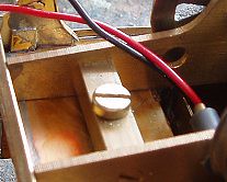
Sometimes this kit isn’t enough though. For example I have always preferred a large file to a small one as it’s easier to file things flat as opposed to a series of small ridges. This was a trick suggested to me by a friend who had witnessed too many people messing around with needle files ‘cos that is what you are supposed to use. I now have three big files on the bench and the smallest is 8 inches long and half an inch wide. The needle files live in the packet most of the time.
Anyway, while fitting the chassis to the G2 I had to enlarge the holes in the spaces that take the bolts. This is a big loco so you use big bolts – simple really. Now the spacers are thick, solid brass and a needle files wouldn’t touch it. Neither would the tapered reamer.
So off to the garage to get the power drill. A Bosch rechargeable if you want to get anoraky about it. A few seconds work and I had a nice large hole in the spacer. Then I cleaned the edges with the countersink bit. Proper job.
Then the retaining nut wouldn’t fit under the footplate so there was the unedifying site of the loco being attacked with the drill as well. I’m sure this isn’t what those photos of proper “craftsmen” show.
It worked a treat though. Perhaps I should keep it within reach at all times. I wonder if a hammer drill would be useful too ?
Wednesday, July 19, 2006
Stop procrastinating
Got to get a move on with this or it will never get finished… Must tackle one of those jobs I keep putting off…
It’s brake gear time again. Since the bits are hidden behind the side frames of the tender they aren’t full of detail. Each hanger and shoe is a single etching – not a lot of depth but enough (for me) with the limited view you get. Besides, this loco is going to run on a garden railway where it will have to deal with slugs and snails on the rails. A friend describes how he had to remove the remains from the inside of a loco once – not pretty.
Once the brakes are on I quickly cleaned the metal, primed it and squeezed the can of matt black spray to get sufficient coverage.
The only change I made to the chassis before painting was to beef up the tops of the outer bearings. While a single thickness of metal should be OK, I have visions of carving a groove in the axle after a few miles of running. A bit of spare etch soldered in at the top should be enough.
Now all I have to do is fit it to the body. Some packing will be needed as the tender is a bit of a “low rider” at present. Nothing that a slice of plasticard won’t cure though.
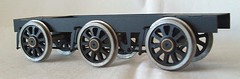
It’s brake gear time again. Since the bits are hidden behind the side frames of the tender they aren’t full of detail. Each hanger and shoe is a single etching – not a lot of depth but enough (for me) with the limited view you get. Besides, this loco is going to run on a garden railway where it will have to deal with slugs and snails on the rails. A friend describes how he had to remove the remains from the inside of a loco once – not pretty.
Once the brakes are on I quickly cleaned the metal, primed it and squeezed the can of matt black spray to get sufficient coverage.
The only change I made to the chassis before painting was to beef up the tops of the outer bearings. While a single thickness of metal should be OK, I have visions of carving a groove in the axle after a few miles of running. A bit of spare etch soldered in at the top should be enough.
Now all I have to do is fit it to the body. Some packing will be needed as the tender is a bit of a “low rider” at present. Nothing that a slice of plasticard won’t cure though.
Saturday, July 15, 2006
Summer time and solder flows easy.
No retail therapy for me today. I decided I didn’t need anything in town that couldn’t be purchased online or in person during the week. This gives me an entire afternoon working on the G2.
Sometimes things just seem to go right. Today was one of those days. The kit parts fitted properly – OK I had to make new tank tops but everything else was fine. Solder generally went where it was supposed to. Maybe it was the heat which must be at least 27 degrees. Not too hot to do stuff outside but very pleasant sat in the shade with the windows open and Guildfest on the radio. It’s days like today I wish I could get into cricket as I’m sure some Radio 4 Long Wave commentary would be very condusive to my workmanship.
I had to put the first whitemetal part in, the massive firebox front casting. Ignoring all good advise I used the 40W iron that was giving good service for the rest of the kit. There wasn’t much chance of melting this beast !
The boiler is level after a slight trim of the smokebox saddle. Because this is such a plain loco I spent a fair bit of time confirming this before finally soldering everything in place. Get it wrong and no amount of work will improve the model.
So for 4 hours work I went from a footplate to something that looks like a steam engine. If I wasn’t going out tonight for beer I’d probably get most of the model built at this rate. Still, I must make my contribution to Gordon’s revenue must I ? Civic duty and all.
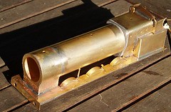
Sometimes things just seem to go right. Today was one of those days. The kit parts fitted properly – OK I had to make new tank tops but everything else was fine. Solder generally went where it was supposed to. Maybe it was the heat which must be at least 27 degrees. Not too hot to do stuff outside but very pleasant sat in the shade with the windows open and Guildfest on the radio. It’s days like today I wish I could get into cricket as I’m sure some Radio 4 Long Wave commentary would be very condusive to my workmanship.
I had to put the first whitemetal part in, the massive firebox front casting. Ignoring all good advise I used the 40W iron that was giving good service for the rest of the kit. There wasn’t much chance of melting this beast !
The boiler is level after a slight trim of the smokebox saddle. Because this is such a plain loco I spent a fair bit of time confirming this before finally soldering everything in place. Get it wrong and no amount of work will improve the model.
So for 4 hours work I went from a footplate to something that looks like a steam engine. If I wasn’t going out tonight for beer I’d probably get most of the model built at this rate. Still, I must make my contribution to Gordon’s revenue must I ? Civic duty and all.
Friday, July 14, 2006
How do you skin a Tomkat ?
Yet again the Tomkat is a bad moggie. Down at the waters edge everything checks out so I lift it onto the water.
And Nothing.
Back out on the table and more nothing. Steering yes, but no drive. Not even an attempt.
Back to the workbench and I poke around inside. As there is no drive I chase the electricity with a multimeter. It’s coming out of the speed control OK. If the motor isn’t plugged in it even comes out of the plug attached to the speed control. Put the motor on and there is nothing again.
So I try the motor on the end of the battery directly. It roars into life for about a second and then nothing. Repeated tries result in sparks at the battery but no life. From years of railway modelling I know this means a short circuit. Something metal has got in there or the motor has started to disintegrate.
But how do I get to motor out to check it ? As far as I can tell the drive system is assembled into the bottom of the boat and the top is heat-sealed in place. Taking screws out doesn’t seem to free anything. I can’t even get the ones out of the front of the motor thanks to the angle they are at. Even if I could the water jacket can’t be loose or it wouldn’t work which means dismantling the cooling system.
Is the motor removable ? Any suggestions ?
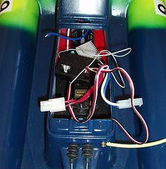
And Nothing.
Back out on the table and more nothing. Steering yes, but no drive. Not even an attempt.
Back to the workbench and I poke around inside. As there is no drive I chase the electricity with a multimeter. It’s coming out of the speed control OK. If the motor isn’t plugged in it even comes out of the plug attached to the speed control. Put the motor on and there is nothing again.
So I try the motor on the end of the battery directly. It roars into life for about a second and then nothing. Repeated tries result in sparks at the battery but no life. From years of railway modelling I know this means a short circuit. Something metal has got in there or the motor has started to disintegrate.
But how do I get to motor out to check it ? As far as I can tell the drive system is assembled into the bottom of the boat and the top is heat-sealed in place. Taking screws out doesn’t seem to free anything. I can’t even get the ones out of the front of the motor thanks to the angle they are at. Even if I could the water jacket can’t be loose or it wouldn’t work which means dismantling the cooling system.
Is the motor removable ? Any suggestions ?
Wednesday, July 12, 2006
Flippin' Freeview
Here’s a job that has been kicking around for a while. I have a Freeview box – great you would think - digital telly with all the exciting channels that brings with it. Trouble is that the top of the TV slopes and so I can’t sit the box on top of it. Apparently you can’t just stick a big nail through the top of both. Something to do with the electrics.
The box can’t go on a separate stand either as there isn’t one. The only place is on the shelf about the TV. But I want to put stuff on there and I don’t mean my lifetime subscription to “TV Quick” magazine !
The solution was obvious. Fix the box underneath the shelf. Knock up some brackets and fix it in position. Easy for anyone with a modicum of skill and a fine selection of tools. I’ve got the tools…
The brackets came from Focus and were bent with the aid of a big vice (stop sniggering out there, the sort you attach to a workbench) and a medium sized hammer. Bend the bracket into a sort of Z shape (look at the photo to see what I mean) and for real finesse, add a couple of soft pads where it will touch the box.
Two brackets were enough, as they just had to push the rubber feet on the box against the shelf. I didn't realise how wonky they were until I looked at the photo. You can't see it form normal angles so I'll leave well alone.All the cables were stuffed in the back and it works well. Apart from the writing on the front being upside down you wouldn’t be able to tell that the device wasn’t meant to be that way.
All done in time for me to catch the final Dr Who of the series. All I needed was an incentive…

The box can’t go on a separate stand either as there isn’t one. The only place is on the shelf about the TV. But I want to put stuff on there and I don’t mean my lifetime subscription to “TV Quick” magazine !
The solution was obvious. Fix the box underneath the shelf. Knock up some brackets and fix it in position. Easy for anyone with a modicum of skill and a fine selection of tools. I’ve got the tools…
The brackets came from Focus and were bent with the aid of a big vice (stop sniggering out there, the sort you attach to a workbench) and a medium sized hammer. Bend the bracket into a sort of Z shape (look at the photo to see what I mean) and for real finesse, add a couple of soft pads where it will touch the box.
Two brackets were enough, as they just had to push the rubber feet on the box against the shelf. I didn't realise how wonky they were until I looked at the photo. You can't see it form normal angles so I'll leave well alone.All the cables were stuffed in the back and it works well. Apart from the writing on the front being upside down you wouldn’t be able to tell that the device wasn’t meant to be that way.
All done in time for me to catch the final Dr Who of the series. All I needed was an incentive…
Tuesday, July 11, 2006
Drive re-connected
The drive shaft fits. Like a good boy I greased it in an effort to repel rust. Carefully fitted it to the boat and then gingerly tested it out of the water.
Nothing. We have steering but no drive. I slacken things off and still nothing. Time for plenty of muttering and poking around in the mechanicals.
Suddenly there is life. A loose connection was the problem. The motor roars and I realise I need to tighten things up again.
I hope this holds. Apparently Ripmax don’t stock this part as a spare. The one Maxx Models got me was a one-off and might not be repeated. Ripmax don’t have an e-mail address either on their site so I don’t hold out much hope. With 5 broken shafts among the clubs boats, the racing might be a bit limited this Sunday.
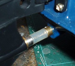
Nothing. We have steering but no drive. I slacken things off and still nothing. Time for plenty of muttering and poking around in the mechanicals.
Suddenly there is life. A loose connection was the problem. The motor roars and I realise I need to tighten things up again.
I hope this holds. Apparently Ripmax don’t stock this part as a spare. The one Maxx Models got me was a one-off and might not be repeated. Ripmax don’t have an e-mail address either on their site so I don’t hold out much hope. With 5 broken shafts among the clubs boats, the racing might be a bit limited this Sunday.
Monday, July 10, 2006
Tape repair
I’ve never repaired a tape before. To be honest, it’s not something I’ll ever make a living out of what with the rise of the CD and all. Still, sometimes you get to try these things.
The demise of the audio cassette has resulted in a lot of people selling them off. Most are rubbish compilation albums but amongst the dross you can find gems. I’ve now nearly completed my collection of “I’m sorry I haven’t a clue” at bargain prices on eBay.
Out of all the tapes I managed to get a single duff one. Obviously rewound far to fast, the tape had broken off from the reel. Not soemthing you spot until it goes back in the player and doesn’t work.
Fortunately in the back of the cupboard holding “things that will come in handy one day”, I had a tape splicing and repair kit. It’s meant to allow you to edit tapes by splicing them together. When I worked for a hospital radio station I fancied having a crack at this. Of course this has now gone the way of the tape as all editing is carried out digitally.
Still I had my kit and once the front and back of the cassette were separate by sliding a sharpish scalpel down the join the tape was re-attached to the reel with the bright yellow sticky tape provided. A little rethreading and touch of glue to put the cassette back together and the tape was as good as new.
It took less time to do than to write and was good fun. I don’t feel half as guilty about the junk in the cupboard. Who knows what I’ll be able to fix next time ?
The tape was very funny too !
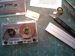
The demise of the audio cassette has resulted in a lot of people selling them off. Most are rubbish compilation albums but amongst the dross you can find gems. I’ve now nearly completed my collection of “I’m sorry I haven’t a clue” at bargain prices on eBay.
Out of all the tapes I managed to get a single duff one. Obviously rewound far to fast, the tape had broken off from the reel. Not soemthing you spot until it goes back in the player and doesn’t work.
Fortunately in the back of the cupboard holding “things that will come in handy one day”, I had a tape splicing and repair kit. It’s meant to allow you to edit tapes by splicing them together. When I worked for a hospital radio station I fancied having a crack at this. Of course this has now gone the way of the tape as all editing is carried out digitally.
Still I had my kit and once the front and back of the cassette were separate by sliding a sharpish scalpel down the join the tape was re-attached to the reel with the bright yellow sticky tape provided. A little rethreading and touch of glue to put the cassette back together and the tape was as good as new.
It took less time to do than to write and was good fun. I don’t feel half as guilty about the junk in the cupboard. Who knows what I’ll be able to fix next time ?
The tape was very funny too !
Sunday, July 09, 2006
Oils well that ends well
Changing oil on an air-cooled Volkswagen is a pretty easy and normally pleasant activity. For relatively little effort you have the glow of satisfaction from a job well done. All the books say regular oil changes are a must so it has to be doing your car some good.
If you want to look after your engine, oil change intervals should be ignored. The true VeeDubber will replace the oil as soon as it starts to become dirty. That way you aren’t sloshing muck around your engine.
My recent issues with the camper have meant that I ignored this sensible advice and my oil was black and horrible. Time to drop it into the can for the recycling centre and put some nice stuff it.
A 21mm socket removes the big drain plug (if you don’t have one of these, change the sump plate when you next change your oil) and after a couple of hours the engine should be empty. Most of it is out after 5 minutes but it’s an excuse to leave the job while pretending it’s being done properly.
The sump plate is unbolted (10mm nuts) and the oil strainer is removed. Everything is cleaned up with white spirit and the muck left over goes into the recycling can. This is the only point things can go wrong – metal shavings on the plate can mean trouble.
Using a 50p change kit consisting of two card gaskets and some cheap washers, reassembly is simple but don’t go mad tightening the nuts in case they pull the studs out of the engine. Then tip oil in the top (2.5 litres) until it makes the middle of the mark on the dipstick. You need to check this after an hour or so as the oil takes a while to seep through the engine to the stick.
Clean up and feel that warm glow of success.
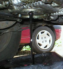
If you want to look after your engine, oil change intervals should be ignored. The true VeeDubber will replace the oil as soon as it starts to become dirty. That way you aren’t sloshing muck around your engine.
My recent issues with the camper have meant that I ignored this sensible advice and my oil was black and horrible. Time to drop it into the can for the recycling centre and put some nice stuff it.
A 21mm socket removes the big drain plug (if you don’t have one of these, change the sump plate when you next change your oil) and after a couple of hours the engine should be empty. Most of it is out after 5 minutes but it’s an excuse to leave the job while pretending it’s being done properly.
The sump plate is unbolted (10mm nuts) and the oil strainer is removed. Everything is cleaned up with white spirit and the muck left over goes into the recycling can. This is the only point things can go wrong – metal shavings on the plate can mean trouble.
Using a 50p change kit consisting of two card gaskets and some cheap washers, reassembly is simple but don’t go mad tightening the nuts in case they pull the studs out of the engine. Then tip oil in the top (2.5 litres) until it makes the middle of the mark on the dipstick. You need to check this after an hour or so as the oil takes a while to seep through the engine to the stick.
Clean up and feel that warm glow of success.
Subscribe to:
Posts (Atom)