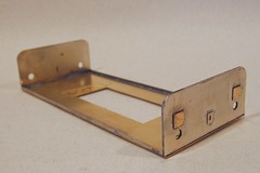
 Now for some big chunks of metal. First the bufferbeams are a two part lamination. I tinned the top and bottom a little and then clamped them together using some clips and ran solder round the edge. A big (50W) iron, lots of flux and taking things slowly did the job - at least they haven't fallen apart yet ! What I hoped is that the heat transfer from the edge soldering would have activated the tinning. If not there is some much at the perimeters they aren't going anywhere.
I deliberately overdid the solder to hide the cusp inevitably found on etched parts. This model locomotive is supposed to be made of solid engineering material not thin wisps of brass and nickel !
Overlays for a couple of plates and the coupling hook surround were sweated on with a gas torch. The iron would work but take longer. Rivets are half etched on the back of the plates. I punched these with a slightly blunted screw with the part face down on a bit of lead. My rivet press only goes up to 7mm rivets and these looked to be man sized versions. Another time I'd consider drilling and soldering a brass pin in the hole to get the size as even these are a bit wimpy.
Much to my surprise the 50 watt iron was man enough to attach the beams to the brass footplate. It worked for the valances too. I couldn't tell on the prototype photos if these were set back at all but on balance I don't think they are. If I'm wrong it's only a tiny amount.
I'll admit to finding a use for the chassis during this job. It was used to jig the buffers into position. I fixed the rear beam and then held the front one against the end of the chassis so I knew it would fit. I've tried other methods but this way guarantees that you don't start hacking at a chassis to get the body on top. Not a problem with this kit but on others I have built in the past. Hmmmmmm.
No comments:
Post a Comment