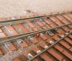
 You gotta love PCB track - if there is one thing it makes easy, it's attaching wires. No need to fiddle around trying to get solder to stick to the side of the rail - especially "entertaining" if the manufacturer has coated with with an anti-oxidation chemical. Me, I just get to solder the wire to the sleeper.
Some people use a bit of copper wire for this and then attached the cored wire to this under the board. I can't see the point of this as it's just another joint to go dry and fail. Maybe if you are using some big fat welding cable to channel your electricity, this might be neater but for those of us employing normal wire, there isn't much to choose. Once the ballast is in place, the wire will be invisible.
In the photo you can see a couple of other things of interest. The point motor wire hasn't been properly cut to length yet. I'm not sure what it's made from but only my biggest wire snips will attack it. In the end a slitting disk in the minidrill completed this. There are motor shafts more cuttable than this material.
The other is the black ended tie-bar. That's permanent pen to stop me soldering the switch rail to the stock one, or at least try to stop this happening !
1 comment:
I know what you mean about the point motor operting rod - a slitting disk is the only way to go, but it does give off some great sparks!
Post a Comment