 Setting up the drive train in a model boat is one of the most important steps during construction. The motor shaft and propshaft should be in as near perfect alignment as possible. Anything less than total trueness will result in vibration, loss of power and noise.
Since perfection is unattainable, we put a coupling in the system. This is either a length of tube to join the two, or for more sophisticated models, a universal joint. This allows the motor to point in a slightly different direction to the propshaft and everything to work OK. The aim should still be as little deflection as possible, but at least the model will work.
My problem is, with the motor mount glued in place and the propshaft likewise fixed, why can't we have more adjustment in the system for fine tuning ?
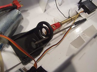
Looking at the Pilot Boat setup, I realised that the holes in the mounting plate were exactly the right size for the screws passing through them. By reaming these out a bit, I could slide the motor around a bit. If I'd realised this earlier, I'd have done the central hole as well.
While on an innovating streak, when I put the crews back in, a tiny O-ring was put inside the face of the mount as well. This held them in place while I added the motor and then, when the screws were tightened, squashed between the plate and motor. My idea was that they would add a flexible coupling between the two, cutting noise. By happy accident, they allow me to alter the angle of the motor to the plate by adjusting the tightness of each screw. Not a lot, but enough to make it worth doing.
Result - I've tuned the drive so it's a lot quieter and hopefully wastes less power producing a noise.
No comments:
Post a Comment