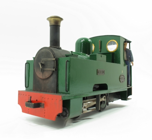
I'm not flush with 16mm scale, 32mm gauge steam engines, but when I suddenly needed one for a photo shoot, it was an opportunity to dig out a model I built well over 25 years ago.
Ben came about because I watched my friend Anthony Coulls chasing a manually controlled live steam engine around a layout. I liked the size and shape of the model. The idea of working a regulator in the cab appealed to me. Chasing a lively steam engine didn't.
I also loved the drawing in the Backwoods Miniatures advert of a Barclay. With this in mind, I sketched out a plan based on some glass-filled nylon driving wheels I had managed to buy. When I made this model, I suspect spending proper cash on a garden railway project was out of the question, so they would have been cheap.
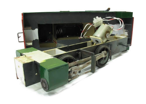
Apart from the slide bars and bearings, the model is a tribute to Plastikard. Nice thick stuff and plenty of it. This seems to have survived some dreadful storage in a plastic box in an unheated shed for many years. I haven't tried the model with batteries (2 C cells) but can't see why the cheapo motor and gears (possible from Proops pound pack) shouldn't work.
The most expensive items on the locomotive will be the nameplates and worksplates. The later read "Philip Parker - 1992". Well, and the chimney which is metal from a source I can't remember.
Inside the body is the clever bit. A sheet of PCB carefully cut so a wiper on the back of the regulator moves around and picks up varying amounts of electricity, this being set by diodes soldered to the board. I have no idea how I worked this out, or why it's diodes and not resistors. I'm sure I couldn't figure it out now.
Direction control is from a slide switch in the footplate.
Ben always worked well, doing exactly what I wanted. I could chase my loco around and operate it from a proper regulator in the cab. I just didn't burn my fingers doing it.


2 comments:
I'm guessing that you don't have the circuit for this stuff - not to worry.
One useful thing about diodes is the way they can sometimes be set up to drop known potential differences ("voltages" to most of us).
(Throwaway thought alert.)
You might remember one BRM project layout a few years back (Ruston Quays?), which featured a Diesel railcar going backwards and forwards, using a Gaugemaster shuttle unit. Well, if the layout had been much longer, I might have been tempted to suggest experimenting with extra track breaks near the ends - and some diodes, to more slowly increase and reduce the voltages (and thus speeds) - with all but the final track break at either end having a pair of diodes connected in inverse parallel.
Saying that, this would have been experimental territory - quite possibly requiring either longer "run-offs", or only one bogie on the railcar to be fitted with pickups.
If I ever get the time, I might have to do a "proof of concept" - using a piece of scrap track on a board, with a very short loco or model tram. Probably don't expect my results any time soon (if at all).
If you connect a small silicon diode in a circuit it drops about 0.6v without generating much heat or taking up much space. Put 5 in a row and you drop 3v off a supply voltage, etc. If anyone remembers speed controllers on old model rc cars you may recall they had chunky power resistors on the speed controllers that were 2-3cm long each and almost 1cm in diameter. These got very hot in use if the car was made to go slow as the voltage drop they cause just gets turned into pure heat.
I suspect you knew or found this out when the loco was built and so went for the small and runs-cool diode solution rather than big chunky wire wound resistors. Diodes are often a cheaper solution too.
Post a Comment